Important changes to repositories hosted on mbed.com
Mbed hosted mercurial repositories are deprecated and are due to be permanently deleted in July 2026.
To keep a copy of this software download the repository Zip archive or clone locally using Mercurial.
It is also possible to export all your personal repositories from the account settings page.
Dependents: PCA9622_LED8x8_Demo PCA9622_LED8x8_Hello PCA9622_LED8x8_x6_Demo shake-shake-machine
Homepage
0. What is this?
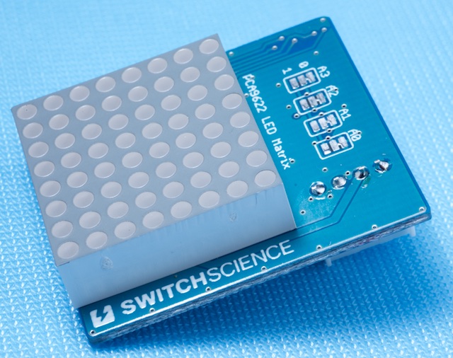
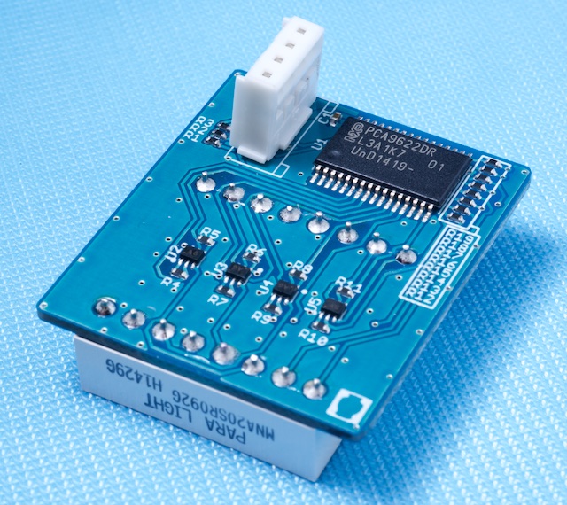
I2C interface single color LED matrix module with PCA9622(LED controller).
This library provides interface from memory array to LEDs, manages scan.
Brightness control can be done for each pixels by setting data as float value (from 0.0 to 1.0).


1. How to use
1.1 Sample code
Import programPCA9622_LED8x8_Hello
This is a very simple sample code for the PCA9622_LED8x8 library. arget hardware : "I2C 8x8 LED matrix board" from Switch Science https://www.switch-science.com/catalog/2071/
1.2 Very basic sample
1.2.1 Displaying static image
Next is simplified code sample that makes still image on the LEDs.
In the main() function, the library operation is started by start() function and image data is set by set_data().
The image data is stored in 2 dimensional float array.
#include "mbed.h"
#include "PCA9622_LED8x8.h"

PCA9622_LED8x8  matrix( p28, p27 );     //  I2C pins. SDA and SCL

int main()
{
    float   image[ 8 ][ 8 ];

    matrix.start();

    //  making 8x8 image to "image" array
    for ( int i = 0; i < 8; i++ )
        for ( int j = 0; j < 8; j++ )
            image[ i ][ j ]   = (i + 1) * (j + 1) / 64.0;

    //  set the image into library internal bufer
    matrix.set_data( image );

    while(1)
        ;
}

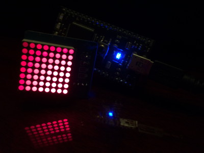
result of upper code
1.2.2 Image array elements' physical position
Each element of "float image[8][8]" array has physical position of..
| left | right | |||||||
|---|---|---|---|---|---|---|---|---|
| top | image[0][0] | image[0][1] | image[0][2] | image[0][3] | image[0][4] | image[0][5] | image[0][6] | image[0][7] |
| image[1][0] | image[1][1] | image[1][2] | image[1][3] | image[1][4] | image[1][5] | image[1][6] | image[1][7] | |
| image[2][0] | image[2][1] | image[2][2] | image[2][3] | image[2][4] | image[2][5] | image[2][6] | image[2][7] | |
| image[3][0] | image[3][1] | image[3][2] | image[3][3] | image[3][4] | image[3][5] | image[3][6] | image[3][7] | |
| image[4][0] | image[4][1] | image[4][2] | image[4][3] | image[4][4] | image[4][5] | image[4][6] | image[4][7] | |
| image[5][0] | image[5][1] | image[5][2] | image[5][3] | image[5][4] | image[5][5] | image[5][6] | image[5][7] | |
| image[6][0] | image[6][1] | image[6][2] | image[6][3] | image[6][4] | image[6][5] | image[6][6] | image[6][7] | |
| bottom | image[7][0] | image[7][1] | image[7][2] | image[7][3] | image[7][4] | image[7][5] | image[7][6] | image[7][7] |
1.2.3 Making the image moving
If you want to perform animation on the LEDs, it can be done by simple loop.
Keep the loop doing (1) store image data into the array and () call set_data() function.
The set_data() function can be called any time.
The set_data() function does copy the data in in-active side of internal buffer.
This library has two 8x8 buffers internally to perform "ping-pong" buffering. One side of the buffer is "active" and other side is "inactive".
The active side is the buffer for displaying data to LEDs. The inactive side is for user access.
The set_data() always access to the inactive side and after the inactive side filling is done, the active/inactive side switched at next scan start.
    while(1)
    {
        //  do something for image array to store data;
        ....
        ...
        matrix.set_data( image );
        wait( 0.1 );
    }
2. Tips
2.1 Frame rate
To minimize the flicker, default setting of frame rate is set to 100Hz.
But it is bit heavy rate to maintain the scan by MCU. If you going to use multiple modules, you may need to lower the I2C clock frequency.
Since mbed's I2C write routine is blocking function, frequent I2C transfer consumes much CPU time (just to wait transfer complete). To draw a line, one I2C transfer is done (14 bytes transfer including slave address). If the frame rate is 100Hz, 800 times I2C transfer happens in a second (8 lines/frame * 100Hz). If your mbed is supporting "I2C Fast mode plus (Fm+)", this will be a good option to reduce the CPU load. PCA9622 supports Fm+ which can handle the clock upto 1MHz.
2.2 Start/Stop
After start() function call, a periodic interrupt is installed to maintain the scanning the LEDs. This will be kept until stop() function called.
3. Links
shop page (Japanese)
schematic
PCA9622
Component page is available
Please refer to the component page for for more information.
Information
If you want to try displaying image which is prepared as file (PNG, JPEG, GIF, BMP, etc.), this tool may be useful.
This tool converts the image data into float array (in C source format).
https://gist.github.com/toyowata/bf576ee091e75071bc66
