Inverse Kinematics
Well, following on from the AX12+ Testing I've been doing I feel that it's time to take a first stab at controlling a group of servos to mimic the walking action of a quadruped. The method I will use to do this will be using Inverse Kinematics, which is the process of stating a end point of a limb and deriving the joint angles given this poistion. This is in contrast to Forward Kinematics which would state the joint angles then derive the limb position. I thought that this would be a better way to work because when I walk I don't think about what angles my hip and knee are at nor do I try to control them, what I focus on is the position and articulation of my foot. I wanted to give the robot the same philosophy.
The Problem With Inverse Kinematics
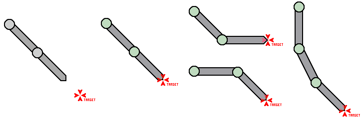
The trouble is that after a bit of research I've concluded that inverse kinematics is rather difficult! But there are a few main reasons why this is not ideal. For example the number of links and the number of solutions as illastraited below.

This illustration shows four situations with no possible solution (far left), a single solution, two solutions, and many/infinite solutions (far right). The next problem is that many of the algorithms that I have looked at (CCD and Jacobian algorithms) seem to be progressive or based on iteration - where I would like a single definitive solution. Finally, and this is really the killer, is the maths... Seriously, I like maths, and most of my friends think I'm a maths geek, but nearly all the papers detailing inverse kinematics seem to be unduly complex. Jacobian vectors, Calculus, matrices, and an unhealthy amount of Greek symbols make these hard enough to follow and given my limited programming experience I have no idea how to begin programming them!?! So I guess I'm going to create my own slightly simpler IK algorithm.
Which Brings Us To The Maths...
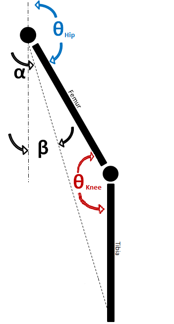
OK so let's start with how I can make it a bit simpler. Assuming that there were only two links and a two joints. Further assume that one of these joints is in a fixed location (but free to rotate). This would be the situation with the image second from the right above, which is stated as having two solutions. Finally it I constrained the limb so that the 'knee' joint could only bend in one direction (much like my - and I suspect your knee!). This would make a limb that looked something like the image below...

I will define the desired end position of the foot with the coordinates X,Y - with 0,0 being the fixed point of the top (hip) joint. Because the length of the Femur and Tibia are fixed and constant, an imaginary line can be traced from the hip joint to the foot position. The length of this line can be calculated using Pythagoras's Theorem, i.e. L = √(X^2 + Y^2). As the lengths of all sides of this new imaginary triangle are now known I can use the Law of cosines to calculate the the angle of the knee, i.e. Θ = Cos-1 (Femur^2 + Tibia^2 - L^2)/(2*Femur*Tibia)
The next thing to calculate is α. This can again be found using the Law of cosines, which now becomes Θ = Cos-1 (Femur^2 + L^2 - Tibia^2)/(2*Femur*L). Finally the angle β can be calculated using trigonometry, i.e. ϒ = Tan-1 X/Y, making the hip angle 180° - α - β.
The Code
So this can be tested as a nice little program to see if it works, something like...
#include "mbed.h"

#define FEMUR 100
#define TIBIA 100
#define Y 100
#define PI 3.1415926

Serial pc(USBTX, USBRX);

int main() {
    pc.printf("\n\rTesting Started...\n");

    for (int X = -50;X<=50;X+=5) {
// Begin by working out L
        float L = (X*X) + (Y*Y);
        L = sqrt(L);

// Work out the Knee angle
        float Knee = (FEMUR*FEMUR)+(TIBIA*TIBIA)-(L*L);
        Knee = Knee / (2*FEMUR*TIBIA);
        Knee = acos(Knee);

// Work out Alpha
        float Alpha = (FEMUR*FEMUR)+(L*L)-(TIBIA*TIBIA);
        Alpha = Alpha / (2*FEMUR*L);
        Alpha = acos(Alpha);

// Work out Beta
        float Beta = (float) X/(float) Y;
        Beta = atan(Beta);

// Finally work out the Hip angle
        float Hip = PI - Alpha - Beta;

// Convert the angles to degrees...
        Knee = Knee * 180 / PI;
        Hip = Hip * 180 / PI;

// Print the answers to terminal
        pc.printf("\n\rX = %d, Hip = %.2f, Knee = %.2f",X,Hip,Knee);
    }

    while (1) {
    }
}
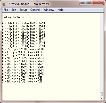
After which the output from the mbed is...

I checked these figures and they seem OK, so I guess that the next step is to physically prove the concept with some servos
Implementation Of The Algorithm
So using some AX12+ servos I have,a pencil and some sellotape, I will hopefully prove that the work done so far is sound. One of the first things that I notice when I start to write the program is that the AX12+ has an oddity where 150° is straight instead of the 180° one would expect! So I'll modify the code to subtract 30° from the final result of each calculated angle.
This actually takes me a little longer to get my head round than I thought as I also notice that the AX12+ servo angle increases in a CCW fashion - so I need to not only subtract 30° to the angles but also subtract the hip angle (as I'm taking this in a CW direction) from 360°... Oops - I'll fix that in a bit maybe?
Anyway, after I measure the Femur and Tibia lengths (100mm & 140mm) I'm ready to test the leg. The test program moves the foot over a distance of 200mm and when raises the foot 5mm on the return stroke. The program is published below.
So using yet more sellotape I strap the leg to a picture frame and run the program. The results are shown below...
So that seems to work OK. A quick check with the tape measure shows that the stride is a tad under 200mm - which is fine. Also it is lifting up a bit on the return stroke as planned. So I'm happy with that!
Next step 3D kinematics...
Please log in to post comments.
