Robo Panorama
Robot to take Panoramic Images
Project by Jinay Dushyant Vora and Lowe Dantzler
Purpose
To design a robot to capture images from all directions (360° around, 90° up and down), and save these images to a portable storage medium, so that they can later be combined into a panorama.
Basic Concept of Panoramic Photography
Panoramic photography is a technique of photography, using specialized equipment or software, that captures images with elongated fields of view. Images captured are termed as panoramic if the aspect ratio of that image is greater than 2:1. To capture such type of images from a camera is not possible. So the steps involved in generating such an image is explained below:
1. Decide the image field of view. Any image having a field of view greater than 160° by 75° is termed as panoramic.
2. Capture multiple images through your normal camera. You can select any view angle but there be at least 20% correlation between any two images. Keeping this amount of correlation helps in combining the images correctly.
3. Forward these images to Special software dedicated to make panoramic images from multiple images.
Description
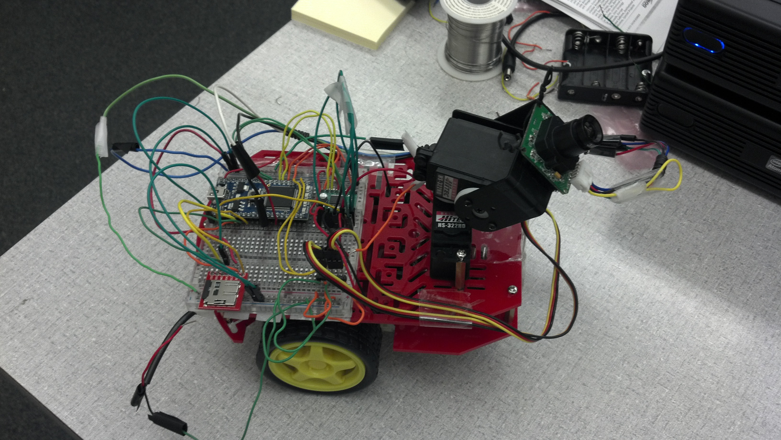
We have designed a robot that which takes images from all directions (360° around, 90° up and down) and store these images on an on-board SD card. This card can be accessed by a user, who can then combine the images into a panorama. The milestones involved in successful completion of this project and how it was done is mentioned below:
1. We interfaced the mbed with the Magician Robot described in the cookbook. The DC motors of this robot were driven by mbed chip via a H-bridge. Since mbed is not capable of supplying enough current to drive the DC motor, a Motor driver circuit called H-bridge is used. Batteries (6V) were used to supply enough voltage.
2. We then interfaced two servo motors with mbed. These servo motors when used together provided rotation on both horizontal and vertical axes. Servos were mounted on top of one another to implement this feature.
3. A camera was placed on top of one Servo motor which captured images from all the directions. These images have 160*120 resolution according to our code. However, the size is adjustable. The reason behind for using this low resolution is maximize the available storage.
4. The images captured by the camera were stored on MicroSD card. This card was also mounted on Magician Robot and interfaced with mbed.
5. Images saved to the SD card can be accessed with a computer. Free-ware software is available to combine these images into a panorama (e.g. PTGui). For the purposes of this guide, we have merely stitched together the recorded images as a proof of concept.
Equipment
- Mbed NXP LPC1768
- Magician Chassis Robot
- Camera_LS_Y201
- MicroSD card
- Dual H-Bridge MD08A
- Two Servo Motors
- Breadboard
- Two groups of four 1.5V batteries (two 6V supplies)
- Jumper Wires
Images
Panoramic Robot

Stitched Image, stitched with MATLAB
Saved images were zero-padded and stitched together in MATLAB, for the sake of illustration. Free-ware software is available to build a panoramic image from these.

Demo
Pin Connections
| MBED | Dual H-Bridge Breakout | Robot DC Motors | Battery |
|---|---|---|---|
| Vin | Vmot | + | |
| GND | GND | - | |
| Vout | Vcc | ||
| PWM B | |||
| BIN 2 | |||
| BIN 1 | |||
| AIN 1 | |||
| AIN 2 | |||
| PWM A | |||
| Vout | /STBY | ||
| AO1 | LEFT RED | ||
| AO2 | LEFT BLACK | ||
| BO2 | RIGHT BLACK | ||
| BO1 | RIGHT RED |
| MBED | SD card |
|---|---|
| p5 (mosi) | DI |
| p6 (miso) | DO |
| p7 (sck) | SCK |
| p8 (cs) | CS |
| MBED | Servo1 | Battery |
|---|---|---|
| p21 | PWM | |
| Vcc | + | |
| GND | GND | - |
| MBED | Servo2 | Battery |
|---|---|---|
| p22 | PWM | |
| Vcc | + | |
| GND | GND | - |
| MBED | Camera_LS_Y201 |
|---|---|
| p13 (TX) | RxD |
| p14 (RX) | TxD |
| VU | Vcc |
| GND | GND |
Program
Import programRoboPanorama
Description.
Problems encountered and Future Steps
A couple problems came up in this design. Each one could be dealt with with future work.
-There was an unknown delay between sending the PWM signal to the servos and the servos moving into position. This was solved by putting a delay of 0.75 seconds between the PWM signals being set and the photo being taken. A better solution might be to use a delay dependent on whether the servo.read method yields a satisfactory output.
-The traction of the tires with the table surface was inconsistent, and this made it difficult to decide how long to run the DC motors, to rotate and reverse the robot into the correct position. This could be solved using closed loop control on a compass output.
Two other problems arose during the design, but were resolved.
-For some reason the servos would not function in concert with the DC motors as long as the motor constructors came after the servo constructors, in the code. The motor constructors had to come first. It is still unclear why this is the case.
-Because of some transient effect, probably due to the SD card sharing a power supply with the H-bridge, the first image actually took two iterations to save successfully. Successful saving was included as a condition for proceeding to the next loop iteration, which solved this problem.
References
http://mbed.org/users/4180_1/notebook/sparkfun-magician-robot-base-kit/
http://mbed.org/cookbook/SD-Card-File-System
http://mbed.org/cookbook/Camera_LS_Y201
http://mbed.org/cookbook/Servo
Please log in to post comments.
