MEMS sensor drivers and tilt-compensated compass using the STEVAL-MKI124V1 header board: LPS331 pressure sensor, LSM303DLHC magnetometer/accelerometer and L3GD20 gyroscope.
I used a header board for an STM MEMS evaluation kit in order to take a look at some common MEMS sensors:
- LPS301: Pressure and temperature sensor
- LG3D20: Gyroscope
- LSM303DLHC: Accelerometer and magnetometer
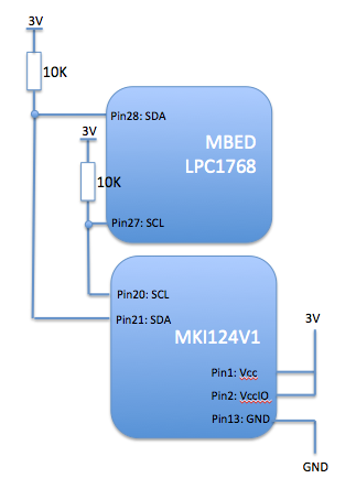
The header was an STEVAL-MKI124V1 which is designed to work with an STM motherboard evaluation system. I took a shortcut and used it with an LPC1768 MBED over I2C
Hook-up was trivial:

The schematic is here:
http://www.st.com/web/en/catalog/tools/PF253482
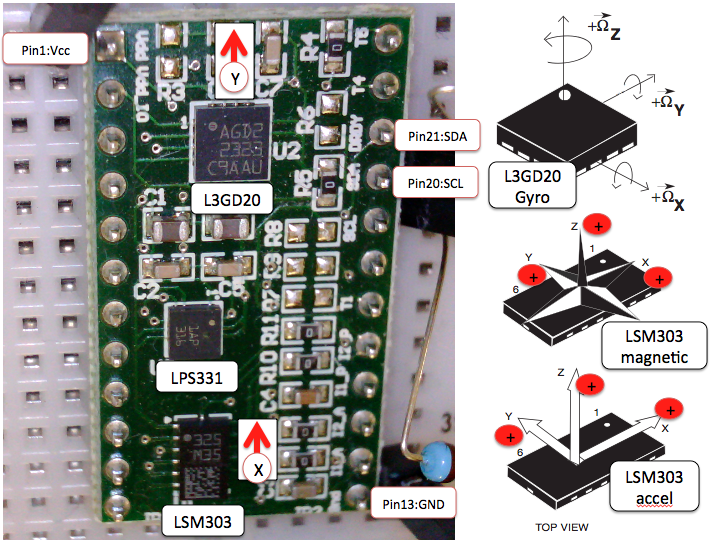
The orientation of the sensors on the board is like this:

The code sets up each of the sensors and then provides a continuous output of temperature, pressure and orientation. Rather than optimize for performance or efficiency, the code here is intended to show clearly how to access the sensors.
An interesting twist was to use the linear accelerometer to find the vector of the earth's gravitational field (i.e. down) and to use that to make a tilt-adjusted compass. Algorithm came from ST Apps note AN3192.
The sensors do need some calibration. Here is a scatter plot of the raw output of X and Y values from the magnetometer:

The chart should be a perfect circle around the origin (allowing for distortion on Excel charting).
- Blue points are the raw data
- Red is offset-corrected
- Green is offset and soft-iron corrected
As you can see, there is an offset error but also and X:Y ratio term. The latter is a soft iron error and is well described in a great article here:
main.cpp
- Committer:
- liamg
- Date:
- 2014-03-18
- Revision:
- 2:2ef63ab235bf
- Parent:
- 1:3b2260aff305
File content as of revision 2:2ef63ab235bf:
// MBED reference code for the ST Micro STEVAL-MKI124V1 header board
// This board has: LPS331 pressure/temperature sensor, L3GD20 gyroscope and LSM303DLHC magnetometer/accelerometer
// Code accesses each of the 3 MEMS sensors and calculates pressure, temp, heading, tilt, roll and angular velocity
// Code is not optimized for efficienecy but instead for clarity of how you use the sensors
// ST application note AN3192 was key in developing the tilt-corrected compass
// Developed on an LPC1768
// By Liam Goudge. March 2014

#define LSM303_on
#define L3GD20_on
#define LPS301_on

#include "mbed.h"
#include "MKI124V1.h"
#include "math.h"

DigitalOut myled(LED1);
Serial pc(USBTX, USBRX);    // tx, rx for USB debug printf to terminal console
I2C i2c(p28, p27);          // LPC1768 I2C pin allocation

// Globals
int16_t const   Offset_mX=-40.0;
int16_t const   Offset_mY=-115.0;
float const     RadtoDeg=(180.0/3.141592654);


char readByte(char address, char reg)
// Reads one byte from an I2C address
// Didn't bother to make a multi-byte version to read in X,Y,Z low/high series of registers because...
// the data registers of all sensors they are in the same XL,XH,YL,YH,ZL,ZH order apart from the magnetometer which is XH,XL,ZH,ZL,YH,YL...
{
    char result;

    i2c.start();
    i2c.write(address);         // Slave address with direction=write
    i2c.write(reg);             // Subaddress (register)

    i2c.start();                // Break transmission to change bus direction
    i2c.write(address + 1);     // Slave address with direction=read [bit0=1]

    result = i2c.read(0);
    i2c.stop();
    return (result);
    }

void writeByte(char address, char reg,char value)
// Sends 1 byte to an I2C address
{
    i2c.start();
    i2c.write(address);         // Slave address
    i2c.write(reg);             // Subaddress (register)
    i2c.write(value);
    i2c.stop();

    }

void initSensors (void)
// Switch on and set up the 3 on-board sensors
{
    pc.printf("--------------------------------------\n");
    pc.printf("\nSTM MEMS eval board sensor init \n");

#ifdef LSM303_on
    // LSM303DLHC Magnetic sensor
    pc.printf("LSM303DLHC ping (should reply 0x48): %x \n",readByte(LSM303_m,mIRA_REG_M));
    writeByte(LSM303_m,mCRA_REG_M,0x94);     //switch on temperature sensor and set Output Data Rate to 30Hz
    writeByte(LSM303_m,mCRB_REG_M,0x20);     // Set the gain for +/- 1.3 Gauss full scale range
    writeByte(LSM303_m,mMR_REG_M,0x0);       // Continuous convertion mode

    // LSM303DLHC Accelerometer
    writeByte(LSM303_a,aCTRL_REG1_A ,0x37); // Set 25Hz ODR, everything else on
    writeByte(LSM303_a,aCTRL_REG4_A ,0x08); // Set full scale to +/- 2g sensitivity and high rez mode
#endif

#ifdef LPS331_on
    // LPS331 Pressure sensor
    pc.printf("LPS331 ping (should reply 0xBB): %x \n",readByte(LPS331addr,pWHO_AM_I));
    writeByte(LPS331addr,pCTRL_REG1,0x90);  // Switch on pressure sensor and select 1Hz ODR. If you select one-shot then sensor powers itself down after every reading...
    writeByte(LPS331addr,pRES_CONF,0x70);   // Temp and pressure noise reduction. Sets # of internal measurements that are averaged to 1 reading. Default is 0x7A (temp rez=128, press=512)
#endif

#ifdef L3GD20_on
    // L3GD20 gyro
    printf("Ping L3GD20 (should reply 0xD4): %x \n",readByte(L3GD20_ADDR,gWHO_AM_I));
    writeByte(L3GD20_ADDR,gCTRL_REG1,0x0F); // Set ODR to 95Hz, BW to 12.5Hz, enable axes and turn on device
    writeByte(L3GD20_ADDR,gCTRL_REG4,0x10); // Full scale selected at 500dps (degrees per second)
    printf("L3GD20 gyro Temp: %x degrees C \n",readByte(L3GD20_ADDR,gOUT_TEMP));
#endif

    pc.printf("--------------------------------------\n \n");
    wait(1); // Wait for settings to stabilize
    }

void LPS331(SensorState_t state)
// Read the pressure sensor
{
    uint8_t             tempL,tempH,pressXL,pressL,pressH;
    int16_t             temp;
    int32_t             press24;
    float               pressure;

    // Measure temperature
    tempL=readByte(LPS331addr,pTEMP_OUT_L);
    tempH=readByte(LPS331addr,pTEMP_OUT_H);
    temp=(tempH << 8) | tempL; // 16-bit 2's complement data

    state.tempC=((float) temp / 480.0) + 42.5; // per equation on page 29 of the spec

    pc.printf("Pressure sensor temperature %.1f degreesC \n",state.tempC);

    // Pressure test
    pressXL=readByte(LPS331addr,pPRESS_OUT_XL);
    pressL=readByte(LPS331addr,pPRESS_OUT_L);
    pressH=readByte(LPS331addr,pPRESS_OUT_H);

    press24=(pressH << 16) | (pressL << 8) | pressXL ; // 24-bit 2's complement data
    pressure = (float)press24/4096.0; // Sensitivity is 4096 LSB per milibar

    pc.printf("Pressure %.1f mbars or %.1f inches Hg\n", pressure, (pressure*0.0295)+0.029);

    }

void LSM303 (SensorState_t * state)
// Magnetometer and accelerometer
{
    char        xL, xH, yL, yH, zL, zH;
    int16_t     mX, mY, mZ,aX,aY,aZ;
    float       pitch,roll,faX,faY;

    xL=readByte(LSM303_m,mOUT_X_L_M);
    xH=readByte(LSM303_m,mOUT_X_H_M);
    yL=readByte(LSM303_m,mOUT_Y_L_M);
    yH=readByte(LSM303_m,mOUT_Y_H_M);
    zL=readByte(LSM303_m,mOUT_Z_L_M);
    zH=readByte(LSM303_m,mOUT_Z_H_M);

    mX=(xH<<8) | (xL); // 16-bit 2's complement data
    mY=(yH<<8) | (yL);
    mZ=(zH<<8) | (zL);

    //pc.printf("mX=%hd   %X          mY=%hd  %X      mZ=%hd  %X      \n",mX,mX,mY,mY,mZ,mZ);

    mX=mX-Offset_mX; // These are callibration co-efficients to deal with non-zero soft iron magnetic offset
    mY=mY-Offset_mY;

    xL=readByte(LSM303_a,aOUT_X_L_A);
    xH=readByte(LSM303_a,aOUT_X_H_A);
    yL=readByte(LSM303_a,aOUT_Y_L_A);
    yH=readByte(LSM303_a,aOUT_Y_H_A);
    zL=readByte(LSM303_a,aOUT_Z_L_A);
    zH=readByte(LSM303_a,aOUT_Z_H_A);

    aX=(signed short) ( (xH<<8) | (xL) ) >> 4; // 12-bit data from ADC. Cast ensures that the 2's complement sign is not lost in the right shift.
    aY=(signed short) ( (yH<<8) | (yL) ) >> 4;
    aZ=(signed short) ( (zH<<8) | (zL) ) >> 4;

    //pc.printf("aX=%hd   %X          aY=%hd  %X      aZ=%hd  %X      \n",aX,aX,aY,aY,aZ,aZ);

    faX=((float) aX) /2000.0; // Accelerometer scale I chose is 1mg per LSB with range +/-2g. So to normalize for full scale need to divide by 2000.
    faY=((float) aY) /2000.0; // If you don't do this the pitch and roll calcs will not work (inverse cosine of a value greater than 1)
    //faZ=((float) aZ) /2000.0; // Not used in a calc so comment out to avoid the compiler warning

    // Trigonometry derived from STM app note AN3192 and from WikiRobots
   pitch = asin((float) -faX*2); // Dividing faX and faY by 1000 rather than 2000 seems to give better tilt immunity. Do it here rather than above to preserve true mg units of faX etc
   roll = asin(faY*2/cos(pitch));

  float xh = mX * cos(pitch) + mZ * sin(pitch);
  float yh = mX * sin(roll) * sin(pitch) + mY * cos(roll) - mZ * sin(roll) * cos(pitch);
  float zh = -mX * cos(roll) * sin(pitch) + mY * sin(roll) + mZ * cos(roll) * cos(pitch);

  float heading = atan2(yh, xh) * RadtoDeg; // Note use of atan2 rather than atan since better for working with quadrants
  if (yh < 0)
    heading=360+heading;

    state->heading=heading;
    state->pitch=pitch;
    state->roll=roll;

    pc.printf("Orientation (deg):       Pitch: %5.1f         Roll: %5.1f          Heading: %5.1f     \n",pitch*RadtoDeg,roll*RadtoDeg,heading);
    pc.printf("Acceleration (mg):       Forward: %5hd       Left: %5hd          Up: %5hd \n",aX,aY,aZ);

}

void    L3GD20(void) // Gyro
{
    char        xL, xH, yL, yH, zL, zH;
    int16_t     gX, gY, gZ;
    float       rorX,rorY,rorZ;

    xL=readByte(L3GD20_ADDR,gOUT_X_L);
    xH=readByte(L3GD20_ADDR,gOUT_X_H);
    yL=readByte(L3GD20_ADDR,gOUT_Y_L);
    yH=readByte(L3GD20_ADDR,gOUT_Y_H);
    zL=readByte(L3GD20_ADDR,gOUT_Z_L);
    zH=readByte(L3GD20_ADDR,gOUT_Z_H);

    gX=(xH<<8) | (xL); // 16-bit 2's complement data
    gY=(yH<<8) | (yL);
    gZ=(zH<<8) | (zL);

    rorX=(float) gX * (17.5/1000.0);    // At 500dps sensitivity, L3GD20 returns 17.5/1000 dps per digit
    rorY=(float) gY * (17.5/1000.0);
    rorZ=(float) gZ * (17.5/1000.0);

    pc.printf("Rate of rotation (dps):  X:%5.1f               Y:%5.1f              Z:%5.1f \n",rorX,rorY,rorZ);
    //pc.printf("gX: %x           gY: %x          gZ: %x \n",gX,gY,gZ);

}

int main()
{
    SensorState_t   state;
    initSensors();

    while(1)
    {

#ifdef LPS331_on
    LPS331(state);
#endif

#ifdef LSM303_on
    LSM303(&state);
#endif

#ifdef L3GD20_on
    L3GD20();
#endif

    pc.printf("\n");
    wait(.5);
    }
}