MEMS sensor drivers and tilt-compensated compass using the STEVAL-MKI124V1 header board: LPS331 pressure sensor, LSM303DLHC magnetometer/accelerometer and L3GD20 gyroscope.
I used a header board for an STM MEMS evaluation kit in order to take a look at some common MEMS sensors:
- LPS301: Pressure and temperature sensor
- LG3D20: Gyroscope
- LSM303DLHC: Accelerometer and magnetometer
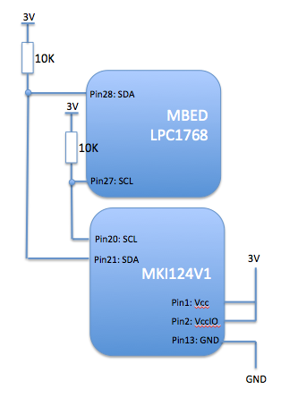
The header was an STEVAL-MKI124V1 which is designed to work with an STM motherboard evaluation system. I took a shortcut and used it with an LPC1768 MBED over I2C
Hook-up was trivial:

The schematic is here:
http://www.st.com/web/en/catalog/tools/PF253482
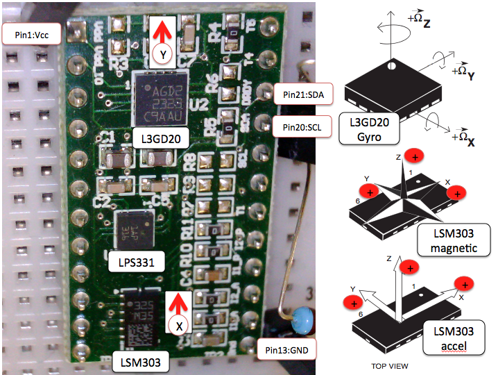
The orientation of the sensors on the board is like this:

The code sets up each of the sensors and then provides a continuous output of temperature, pressure and orientation. Rather than optimize for performance or efficiency, the code here is intended to show clearly how to access the sensors.
An interesting twist was to use the linear accelerometer to find the vector of the earth's gravitational field (i.e. down) and to use that to make a tilt-adjusted compass. Algorithm came from ST Apps note AN3192.
The sensors do need some calibration. Here is a scatter plot of the raw output of X and Y values from the magnetometer:

The chart should be a perfect circle around the origin (allowing for distortion on Excel charting).
- Blue points are the raw data
- Red is offset-corrected
- Green is offset and soft-iron corrected
As you can see, there is an offset error but also and X:Y ratio term. The latter is a soft iron error and is well described in a great article here:
MKI124V1.h
- Committer:
- liamg
- Date:
- 2014-03-18
- Revision:
- 0:91b1274ec397
File content as of revision 0:91b1274ec397:
// Defines for the MEMS sensors on the STEVAL-MKI124V1 board
// Liam Goudge. March 2014

// LPS331AP MEMS pressure and temperature sensor
#define LPS331addr      0xBA // I2C address of the sensor for writes (line SAO is tied high on this board so bit 1=1. Note this may not work on other boards).

#define pWHO_AM_I        0x0F // "ping" register. Device will respond even when in sleep mode
#define pRES_CONF        0x10 // Reset value is 0x7A (512 pressure samples and 128 temperature samples)
#define pCTRL_REG1       0x20
#define pCTRL_REG2       0x21
#define pCTRL_REG3       0x22
#define pPRESS_OUT_XL    0x28
#define pPRESS_OUT_L     0x29
#define pPRESS_OUT_H     0x2A
#define pTEMP_OUT_L      0x2B // Temperature data. 2's complement. Device will respond when in sleep mode
#define pTEMP_OUT_H      0x2C

// LSM303DLHC MEMS ascceleratometer, magnetometer and temperature sensor
#define LSM303_m        0x3C // I2C base address of the magnetometer sensor
#define LSM303_a        0x32 // I2C base address of the accelerometer sensor

// Magnetometer registers
#define mCRA_REG_M       0x00 // Magnetic sensor configuration register A
#define mCRB_REG_M       0x01 // Magnetic sensor configuration register B
#define mMR_REG_M        0x02 // Magnetometer mode register
#define mOUT_X_H_M       0x03 // X-axis magnetic field data High byte
#define mOUT_X_L_M       0x04 // X-axis magnetic field data Low byte
#define mOUT_Z_H_M       0x05 // Z-axis magnetic field data High byte
#define mOUT_Z_L_M       0x06 // Z-axis magnetic field data Low byte
#define mOUT_Y_H_M       0x07 // Y-axis magnetic field data High byte
#define mOUT_Y_L_M       0x08 // Y-axis magnetic field data Low byte
#define mSR_REG_M        0x09 // Magnetometer status register
#define mIRA_REG_M       0x0A // ID register A. Should read 0x48
#define mCTRL_REG1_A     0x20
#define mTEMP_OUT_H_M    0x31 // Magnetometer temperature register High byte
#define mTEMP_OUT_L_M    0x32 // Magnetometer temperature register Low byte

// Accelerometer registers
#define aCTRL_REG1_A     0x20 // Accelerometer output data rate ODR, low power modes etc
#define aCTRL_REG4_A     0x23 // Accelerometer full scale selection etc
#define aOUT_X_L_A       0x28 // Accelerometer X axis low byte
#define aOUT_X_H_A       0x29 // Accelerometer X axis high byte
#define aOUT_Y_L_A       0x2A // Accelerometer Y axis low byte
#define aOUT_Y_H_A       0x2B // Accelerometer Y axis high byte
#define aOUT_Z_L_A       0x2C // Accelerometer Z axis low byte
#define aOUT_Z_H_A       0x2D // Accelerometer Z axis high byte

// L3GD20 MEMS gyro. 3 axis angular rate sensor
#define L3GD20_ADDR     0xD6 // I2C base address of the gyro

#define gWHO_AM_I        0x0F // Ping register. Response is 0xD4. Responds even when device is off
#define gCTRL_REG1       0x20 // Sets Output Data Rate, Bandwidth and Power mode
#define gCTRL_REG4       0x23 //
#define gOUT_TEMP        0x26 // Temperature data. 8 bit resolution
#define gOUT_X_L         0x28 // X-axis angular rate low byte expressed as 2's complement
#define gOUT_X_H         0x29 // X-axis angular rate high byte
#define gOUT_Y_L         0x2A
#define gOUT_Y_H         0x2B
#define gOUT_Z_L         0x2C
#define gOUT_Z_H         0x2D


// Structs
typedef struct{
    float   pitch;
    float   roll;
    float   Xrotation;
    float   Yrotation;
    float   Zrotation;
    float   heading;
    float   tempC;
    float   pressuremB;
    } SensorState_t;