Creating A Remote Controlled Spy Bot
Quote:
Quote:
This is a project for the Georgia Tech class ECE 4180 (Embedded Systems Design) with Dr. Hamblen.
Team Members:
- Landon Ballard
- Alex Jossart
- Sriharsha Singam
Parts Used:
- Mbed LPC1768
- Raspberry Pi 4
- USB Webcam
- Xbox or Playstation Remote Controller (Will need DS4 Windows for Playstation control)
- Bluetooth Module HC-06
- Class D Audio Amp
- Twin Motors (5v)
- Two Wheels
- 7805 Voltage Regulator (and 2 electrolytic capacitors)
- Four LEDs
- LIDAR VL53L0X
- H-Bridge
- Speaker
- Power supply - the power supply chosen will vary, but for this project, 3 cellphone battery banks and 4 AA batteries with a barrel jack attachment are being used. The Pi4 is being powered by a dual male to single female USB connector that is plugged into two cellphone battery banks and the mbed is being powered by just one. The motors and speaker use the AA batteries.
You may also need some sort of counterbalance weight to make sure the chassis is balanced, this project used 6 AAA batteries taped together to balance weight.
This page will demonstrate how to construct an mbed powered, gamepad controlled, wireless spybot using minimal parts.
Pinouts:
Raspberry Pi 4
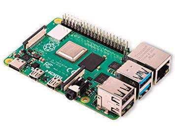
| Raspberry Pi 4 | Web Cam |
|---|---|
| Usb Port | Usb Camera Cable |
To get live video follow this simple tutorial on Hackster.io. Change the input parameters on the configuration file to be whatever frame rate and resolution that is desired. Keep in mind higher resolutions result in higher latency and higher frame rates consume more processor time if there will be other things running on the pi.
You can use any generic USB webcam for this project.
Note that as of 2018, ffserver is no longer supported so in order to get this to work you need to install commit version 2ca65fc, aside from this the process is the same
Bluetooth Module HC-06
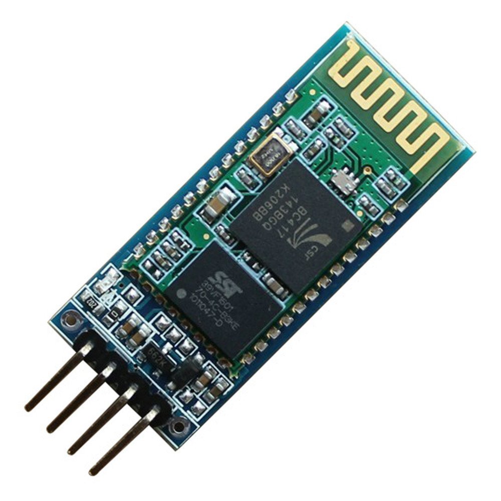
| Mbed | HC-06 |
|---|---|
| Vu (5V) | VCC |
| GND | GND |
| p14 | Tx |
| p13 | Rx |
To get this to work you need to pair it to a windows computer. Once paired, it will automatically open a COM port through the Bluetooth connection. To view the COM port number, go to Bluetooth in settings, then click "More Bluetooth options" then "COM ports" to see the number. Use this number as the serial port in your C# program. Make sure to use "Outgoing" not the "Incoming" field. The "Incoming" field is for receiving signals back from the receiver.
Note:
*The C# program connects to a COM port opened by the HC-06 chip.
*Default pin to pair the HC-06 is 1234.
*The C# program uses default windows libraries.
*Sends data as character strings.
Class D Audio Amp
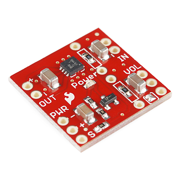
| Mbed | Class-D Audio Amp | Battery | Speaker |
|---|---|---|---|
| p5 | S (pull low with 180ohm) | ||
| p23 | ln+ | ||
| GND | ln- | ||
| PWR+ | 5v from voltage regulator on batteries | ||
| GND | PWR- | ||
| Out+ | Spkr+ | ||
| Out- | Spkr- |
The Class D Audio Amp allows the speaker to play tones. It must have either a 5v or 3.3v source connected to it. In this configuration, the mbed cannot supply enough power while the LIDAR and Bluetooth module are connected. It needs to be connected to the 6V battery pack through a voltage regulator which steps it down to 5v. The speaker plays a short tone when the LIDAR detects that it is near a wall.
Further information on the Class D Audio Amp can be found here : https://os.mbed.com/users/4180_1/notebook/tpa2005d1-class-d-audio-amp/
TOF Sensor VL53L0X
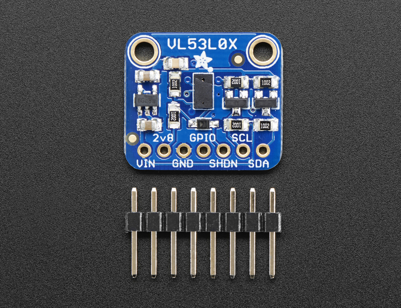
| Mbed | VL53L0X |
|---|---|
| p28 | SDA |
| p27 | SCL |
| p26 | shdn |
| Vout(3.3V) | VCC |
| GND | GND |
The VL53L0X Time of Flight sensor reads in data from the front of the bot and makes distance measurements in millimeters.
The library being utilized in this project can be found here: https://os.mbed.com/teams/ST/code/VL53L0X/ Further information about the LIDAR can be found here: https://learn.adafruit.com/adafruit-vl53l0x-micro-lidar-distance-sensor-breakout/overview
H-Bridge
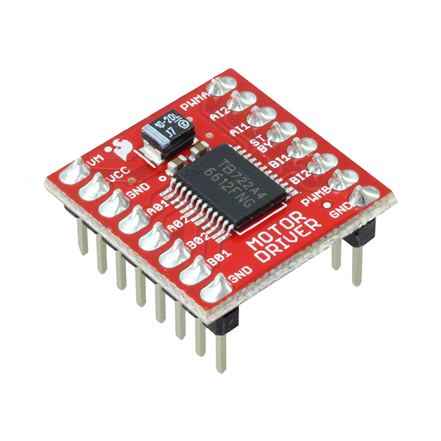
| Mbed | H-Bridge | Motors | Battery | ||
|---|---|---|---|---|---|
| VM | Batteries + (6V from the AA battery pack) | ||||
| Vout(3.3V) | VCC | ||||
| GND | All GNDs | ||||
| A01 | Black on Right Motor | ||||
| A02 | Red on Right Motor | ||||
| B01 | Black on Left Motor | ||||
| B02 | Red on Left Motor | ||||
| p21 | PWMA | ||||
| p8 | AI1 | ||||
| p7 | AI2 | ||||
| Pull high to Vout(3.3V) with a 180ohm resistor | STBY | ||||
| p9 | BI1 | ||||
| p10 | BI2 | ||||
| p22 | PWMB |
The H-Bridge Driver Circuit allows for forward and reverse motion of the motors on the bot. It takes in 6V from the batteries and uses that to boost the power signals from the mbed to control the twin DC motors with PWM.
Further information about H-bridges and other driver circuits can be found here: https://os.mbed.com/users/4180_1/notebook/relays1/
LEDs
| Mbed | LEDs Purpose |
|---|---|
| GND | All GNDs |
| p15 | Green 1 |
| p16 | Green 2 |
| p18 | Red 1 |
| p19 | Red 2 |
The LED's can be placed wherever the user desires. They are made to flash when the LIDAR detects that the bot is near a wall.
Chassis
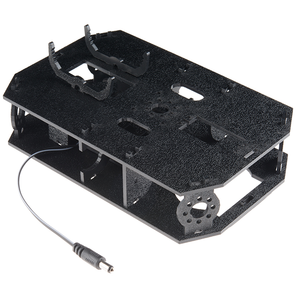
The Sparkfun Shadow Chassis was used for this project.
Assembly instructions can be found here : https://learn.sparkfun.com/tutorials/assembly-guide-for-redbot-with-shadow-chassis
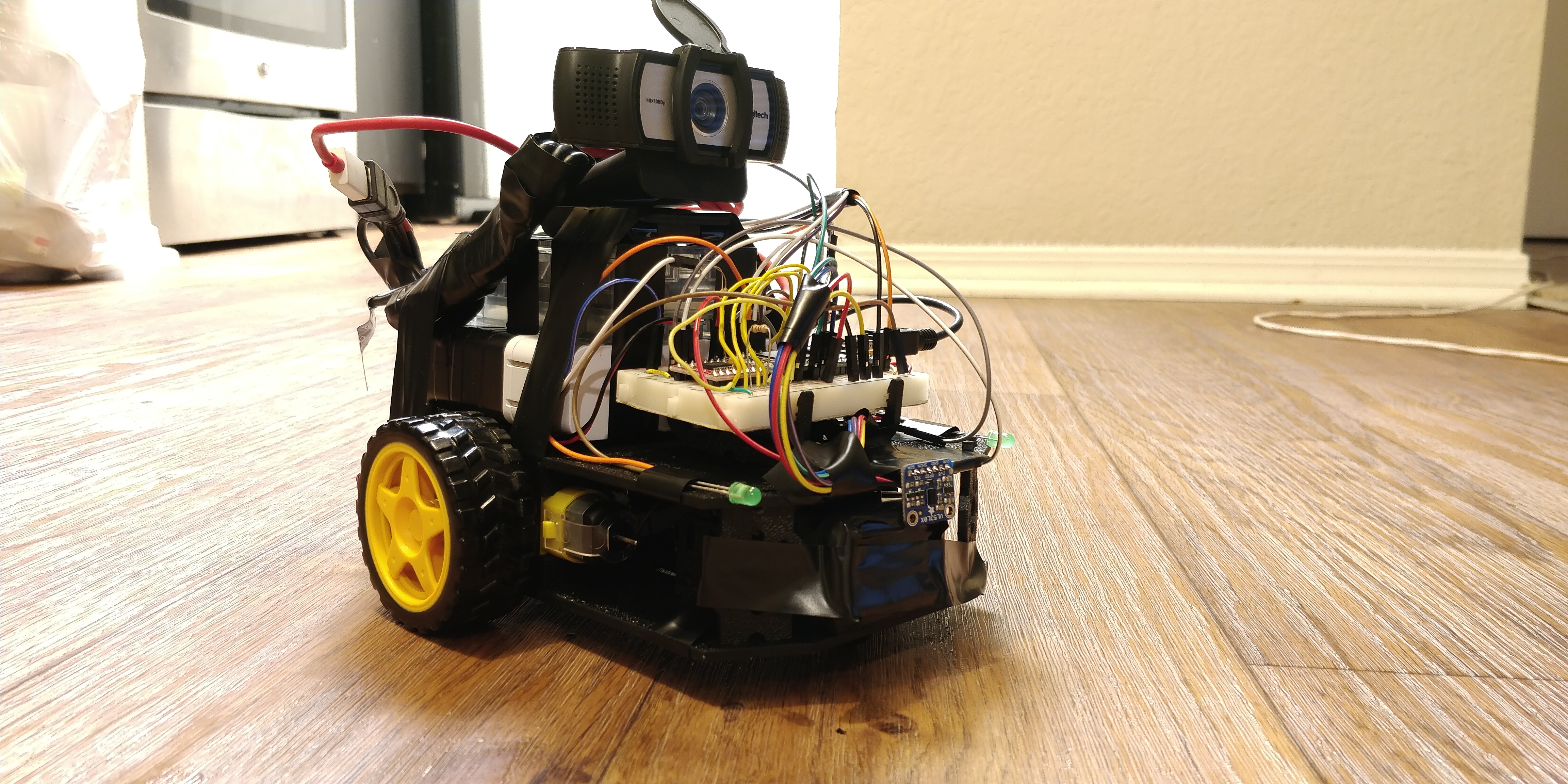
Once assembled, placement of various hardware components on the chassis is up to the end user. Feel free to experiment to find the solution that works best for your needs.
SpyBot Fully Assembled
Code running on the mbed
Import programMbedSpyBotFinalRevision
Twin Motor Spybot using Mbed with bluetooth connection to a PC
C# Program
Note: To use this program Windows Universal Libraries are required. To enable these, unload your project and edit it. After the file alignment section add one line <TargetPlatformVersion>10.0</TargetPlatformVersion>. Then reload the project and select add a reference. After doing this you need to add Windows.Gaming and System.Runtime.WindowsRuntime.dll then you will be set up.
C# Windows Program that Connects to an Xbox Controller
using System;
using System.Collections.Generic;
using System.ComponentModel;
using System.Data;
using System.Diagnostics;
using System.Drawing;
using System.Linq;
using System.Text;
using System.Threading.Tasks;
using System.Windows.Forms;
using Windows.Gaming.Input;

namespace xboxController
{
    public partial class Form1 : Form
    {
        Gamepad Controller;
        Timer t = new Timer();


        public Form1()
        {

            InitializeComponent();
            serialPort1.Open();
            openit("http://youripaddresshere/test.mjpg");
            t.Tick += T_Tick;
            t.Interval = 50;
            t.Start();

        }
        private void T_Tick(object sender, EventArgs e)
        {
            if(Gamepad.Gamepads.Count > 0)
            {
                Controller = Gamepad.Gamepads.First();
                var Reading = Controller.GetCurrentReading();
                double LY = -Reading.LeftThumbstickY;
                //double LX = Reading.LeftThumbstickX;
                double RY = -Reading.RightThumbstickY;
                //double RX = Reading.RightThumbstickX;
                //double RT = Reading.RightTrigger;
                //double LT = Reading.LeftTrigger;
                serialPort1.Write("L" + RY.ToString("0.00"));
                serialPort1.Write("R" + LY.ToString("0.00"));


                switch (Reading.Buttons)
                {
                    case GamepadButtons.A:
                        serialPort1.Write("A");
                        break;
                    case GamepadButtons.B:
                        serialPort1.Write("B");
                        break;

                }
                    Debug.WriteLine("R" + LY.ToString("0.00"));
                    Debug.WriteLine("L" + RY.ToString("0.00"));


            }
        }
        private void Form1_Load(object sender, EventArgs e)
        {

        }

        public static void openit(string x)
        {
            System.Diagnostics.Process.Start("cmd", "/C start" + " " + x);
        }
    }
}
Video Demonstration
Please log in to post comments.
