TY51822r3 Current Consumption using nRF51_WakeUp library
Simple English explanation is bottom area.
updated on June 11th, 2016
Added low-power library (nRF51_LowPwr) for reduce Idle current at normal operating condition.
1.始めに
nRF51の省電力は色々なWebページで紹介されています。
例えば、このページにはどのような手段が有効なのかが、総合的に分析して述べられいます。
https://devzone.nordicsemi.com/question/5186/how-to-minimize-current-consumption-for-ble-application-on-nrf51822/
しかし個別の対応は判ったような気になるのですが、いざそれらを具体的なプログラムで実現しようとすると、簡単ではありません。
このノートブックに結論を書ければ良かったのですが、残念ながらまだ満足できる結論に至っていません。
しかしながら、外部RTCなどを接続せずに内部RTCを使用して582時間までの任意の時間帯でDeep Sleepモードに入り休止することが出来る機能に目処が立ちましたので、このDeep Sleepモード内での電流値は不満が残りますが公開としました。
現在のDeep Sleep時の電流は80μA程度で、本来はこの値の十分の一程度までいける可能性があるのではないでしょうか?
皆さんの知恵を拝借する意味でもプログラムを公開します。
2.何が出来るか?
nRF51_WakeUpライブラリーは、2つのポートを占有使用し内部RTC1のコンペアマッチ機能で指定時間眠りについて、その後リセット状態から再起動します。
このライブラリーを使用すれば省電力を最大限に生かしながら、長期の定期的な動作が可能で、データ収集のように一定時間間隔で動けばよい時に便利です。
3.ハードウェアと再起動方法
ポートは2つ使用します。ひとつのポートはRTC1のカウンターがコンペアレジスタと一致した際に、出力がLowからHiに変わる出力ポートです。
もうひとつのポートは、割り込み入力端子でLowからHiに変化した際に割り込みを検出します。
2つのポートは、外部で接続しておきます。
本来はRTC1のコンペアマッチで直接割り込みを発生させれば、2つのポートは不要になって便利なのですが、mbedでRTC1をTickとして使用している関係で割り込み処理ルーチンがmbed内で制御されているため、ユーザー側で自由に使用できません。
勿論、mbed-devのソースファイル付ライブラリーで修正して使う方法も考えたのですが、先ずはmbedライブラリーで動作させることを目指しました。
RTC0はBLE制御でSoftDeviceが使用しているので、こちらも使用できません。nRF52はRTC2もあるので将来的にはこのRTC2を使用すれば外部ハードウェアなしで対応できるでしょうが、nRF51ではRTC1を使用するしかありません。
残念ながらRTC1のコンペアマッチはそのまま出力ポートに直結は出来ません。
そこでコンペアマッチで発生するEventをPPIのEEP(Event-End-Point)へ接続して、それをトリガーとしてTEP(Task-End-Point)へつなぎ、ポート出力とします。
割り込みが起これば何も考えずにシステムをリセット起動します。
サンプルプログラムでは、下記のようになっています。
part_of_main.c
nRF51_WakeUp wakeup(LED1, P0_0);
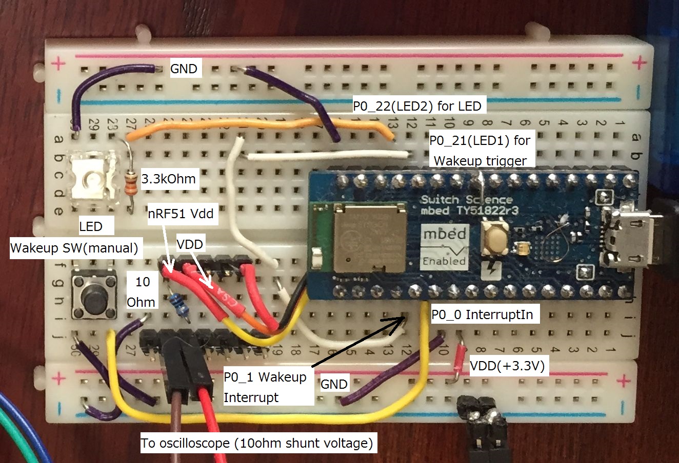
この場合には、LED1(P0_21)とP0_0を接続します。P0_21がRTC1で発生したコンペアマッチでLoからHiに変化します。
それをP0_0をInterruptInで受けて再起動用の割り込みを発生します。
RTC1のCC[0]でP0_21を変化させる部分は、下記のようになります。
part_of_nRF51_WakeUp.cpp
    // GPIOE
    NRF_GPIOTE->CONFIG[0] =
          (GPIOTE_CONFIG_POLARITY_LoToHi << GPIOTE_CONFIG_POLARITY_Pos)
        | (p_name_trgr << GPIOTE_CONFIG_PSEL_Pos)
        | (GPIOTE_CONFIG_MODE_Task << GPIOTE_CONFIG_MODE_Pos);
    // Set PPI
    NRF_PPI->CH[0].EEP = (uint32_t)&NRF_RTC1->EVENTS_COMPARE[0];
    NRF_PPI->CH[0].TEP = (uint32_t)&NRF_GPIOTE->TASKS_OUT[0];
4.現在の問題点
DeepSleep状態で約80μA程度となっていますが、十分な値とは思えません。
色々と多試行錯誤を繰り返したのですが、その先が見えません。通常動作時のアイドル電流は少なくてもSleepよりも少ないという逆転現象が起きていますので、原因が判れば数μA程度まで下げられると思われます。
例えば、
sd_power_system_off()
はNordicが提供する省電力にするために簡単に呼び出せるSoftDeviceですが、再起動できません。
この状態では、数μAレベルまで電流を抑える事が出来ますし、外部スイッチを付けて割り込みを発生させれば起動できますので、RTC1でなく外部のRTCで割り込みをかければ、このモードが使えます。
まだ公開していませんが、この使い方でデーターロガーを製作中です。
5.電流測定の難しさ
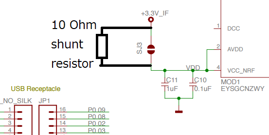
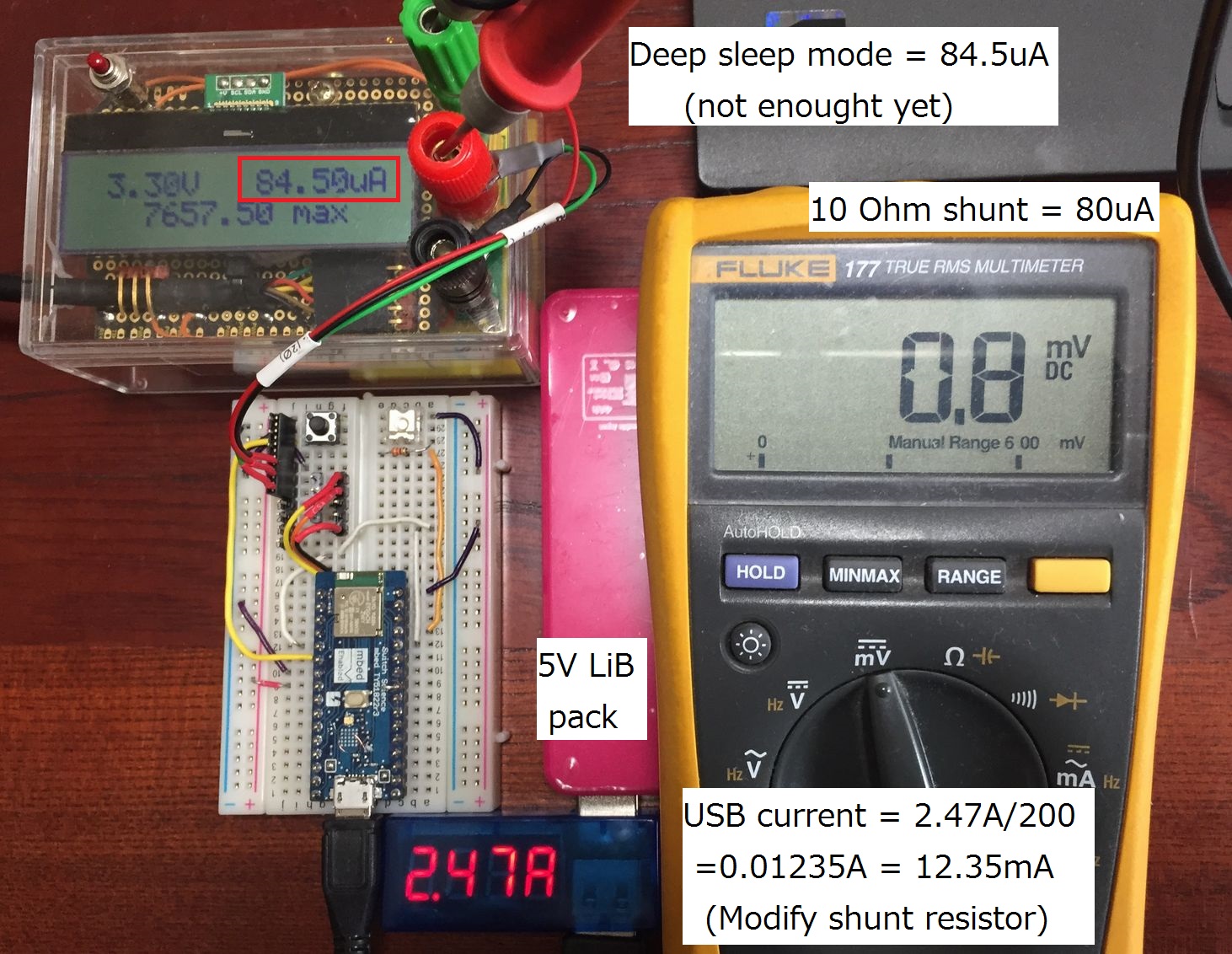
電流測定は3つの方法を適時使用しています。基本的には10Ωの抵抗を下記のように挿入してその両端の電圧測定をしています。
TY51822r3のボードは下記のように裏面にはんだジャンパーがあるので、そこのはんだを取り除き抵抗をつけます。
1)デジボルによる測定(最少分解能0.1mV→100μA)
2)Analog Discoveryのオシロスコープ機能
3)自作電流計(INA226チップ利用)分解能50nA /users/kenjiArai/code/INA226/
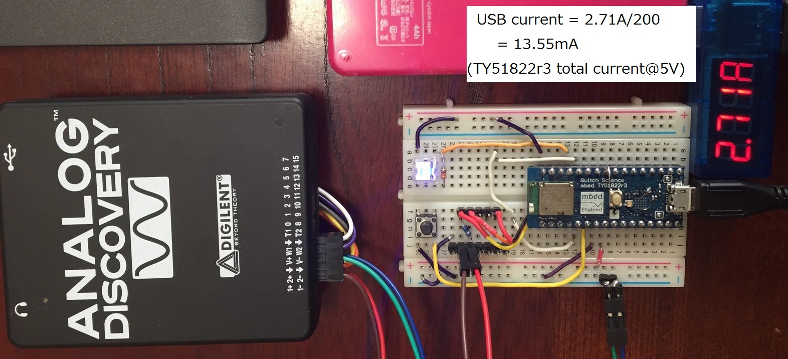
測定は下記のように行っていますが、はっきり言って良い測定器を持たない私のような素人には難しい作業です。
 下記を忘れずに!
問題と注意点
nRF51がDebug Mode時にはDeepSleep時の電流がNormal Mode時より大幅に増加する点です。
https://devzone.nordicsemi.com/question/17282/nrf51822-swdioswdclk-internal-pull-resistors/
ソフトウェアを書き換えた際には、一度USBを抜いてDebugモードからNormalモードにする必要があります。
6.サンプルプログラム
Import programBLE_LoopbackUART_low_pwr_w_RTC1
You can control from iPhone and put some command. h=show commands help, v=show TY51822r3 VDD data, t=show chip temperature, q=you can make deep sleep condition.
プログラムは、Uartで交信します。
私はiPhoneでテストしました。
nRF UART by Nordic
https://itunes.apple.com/us/app/nrf-uart/id614594903?mt=8
iPhoneからも’q’を送るとDeep Sleep状態に移ります。
CentralからUartコマンドとして各種データを要求して、次のようなコマンドで、
q 3600 (サンプルプログラムは現在このようには動作しない)
一時間後に再開するような形にするとかなり省電力になるでしょう。
ハードは下記のように接続しています。
電流は、USBで送られる+5VラインではDeep Sleep状態でも10数mA流れます。
これはCMSIS-DAP&USB Virtual COM portを制御しているI/Fチップの消費電流も含まれているためです。
最終的には、USBからの給電ではなくコイン電池でBLEモジュールのみに電源供給をしないといけません。
またサンプルプログラムにはスイッチがつけられていて、手動でも再起動が出来ます。
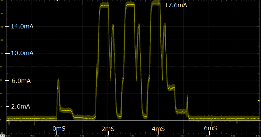
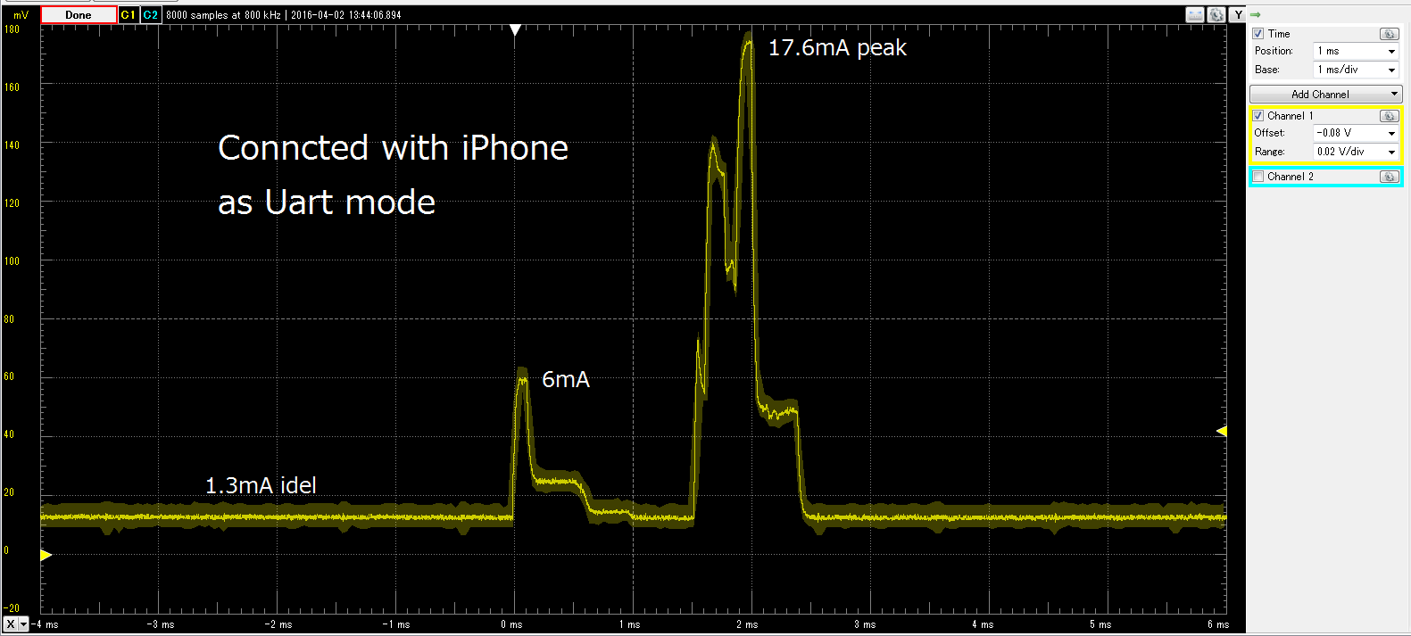
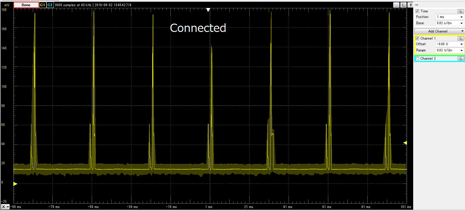
電流波形
correction 176mA -> 17.6mA
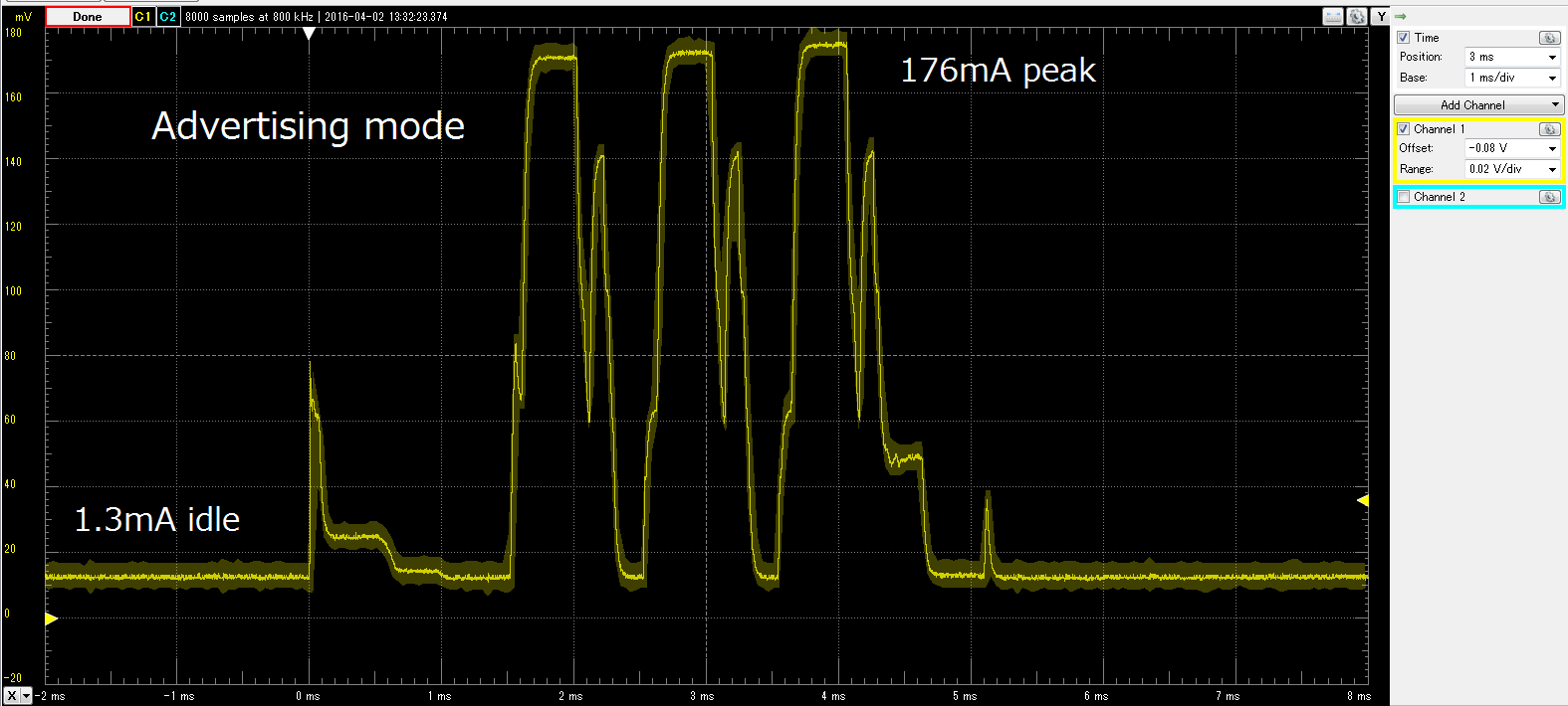
Reduce Idle current (Please compare above and below (June 11th, 2016).
Use nRF51_LowPwr library.
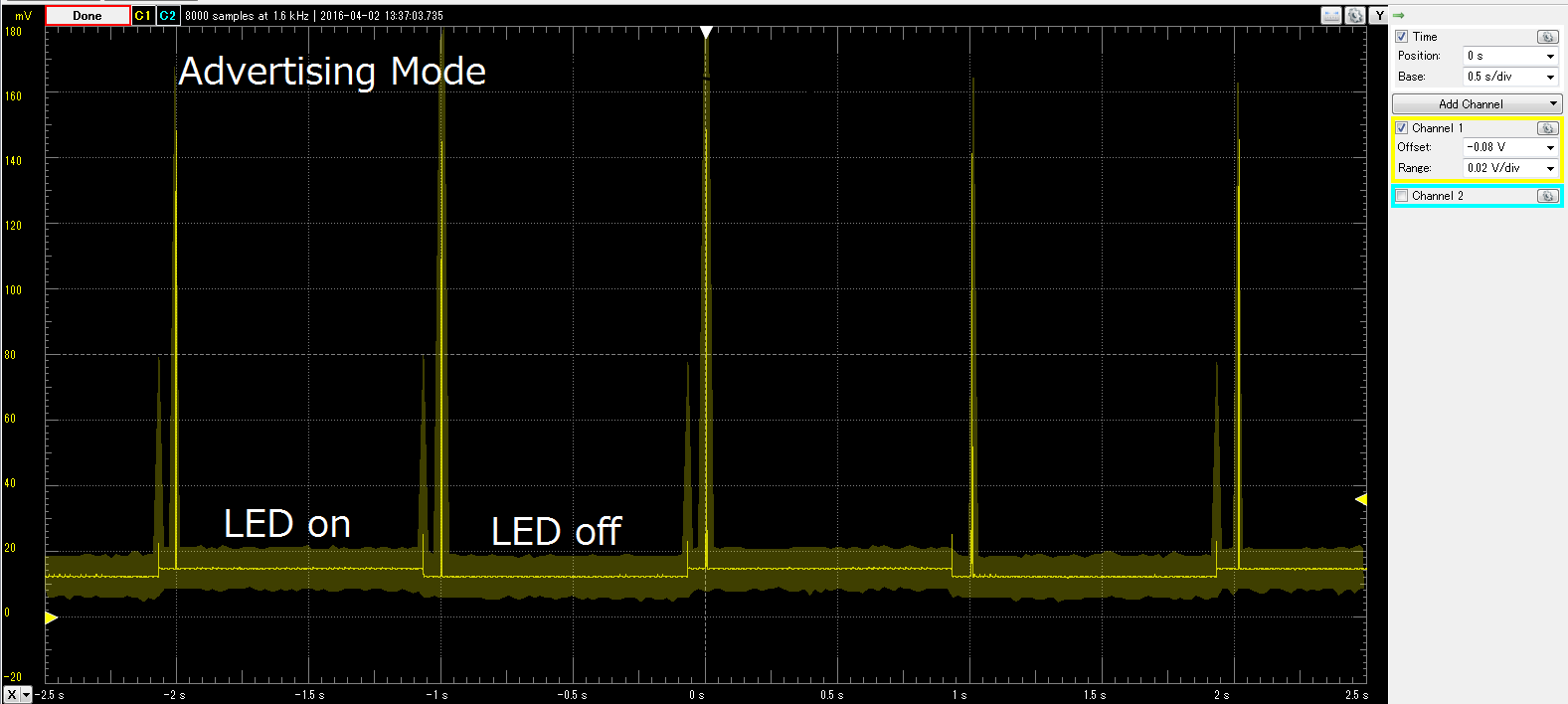
correction idel->idle
a. Motivation
nRF51 current consumption issue is very popular and you can see several Web pages.
For example, this is very good answer as comprehensive and deep analysis report.
https://devzone.nordicsemi.com/question/5186/how-to-minimize-current-consumption-for-ble-application-on-nrf51822/
But if you try to make a program, there are so many issues which you need to solve and to think how to put each peaces and those order.
I have NOT achieved good current consumption at deep-sleep mode yet.
Reason for disclosing the program even not good current consumption result is that I would like to get your advice and suggestion.
nRF51_WakeUP library can enter "DeepSleep mode" with your suitable time (2 sec to less than 582 hours).
I hope this program can use for low power operation such as every 1 hour collecting data and send the data to central station.
b. What kind of function?
The library use two external port for RTC1 compare match and interrupt trigger.
When time is up, RTC1 makes a trigger for interrupt then call system reset routine.
nRF51 restart same as "RESET" condition.
c. Hardware configuration and restart method
One port is for RTC1 compare match output. Normal state is Low(normal) then go to High(Trigger) when RTC1 counter equal to compare reg value.
Another port is for Interrupt input.
Interrupt is happen when input is rise from low to high.
Therefor you need to connect two ports!!
Easiest way is that RTC1 compare match interrupt is used and not to assign two port but I cannot do it because mbed uses RTC1 as tick timer and those interrupt handler is in mbed system.
RTC1 does not have direct control port for the compare match event.
From this restriction, I connected RTC1 CC event to PPI EEP(Event-End-Point) then TEP(Task-End-Point) connected to output port.
Example program is here.
part_of_main.c
nRF51_WakeUp wakeup(LED1, P0_0);
LED1(P0_21) connected P0_0.
RTC1 compare match event makes P0_0 output port low to high.
P0_0 will be high then interrupt routine will call system reset routine.
Program sets RTC1 CC event and P0_21(p_name_trgr) as follows.
part_of_nRF51_WakeUp.cpp
    // GPIOE
    NRF_GPIOTE->CONFIG[0] =
          (GPIOTE_CONFIG_POLARITY_LoToHi << GPIOTE_CONFIG_POLARITY_Pos)
        | (p_name_trgr << GPIOTE_CONFIG_PSEL_Pos)
        | (GPIOTE_CONFIG_MODE_Task << GPIOTE_CONFIG_MODE_Pos);
    // Set PPI
    NRF_PPI->CH[0].EEP = (uint32_t)&NRF_RTC1->EVENTS_COMPARE[0];
    NRF_PPI->CH[0].TEP = (uint32_t)&NRF_GPIOTE->TASKS_OUT[0];
d. Known problems
Latest result is around 80uA at DeepSleep Mode.
This is NOT enough and I believe we can reduce one tenth (at least less than 5uA) .
e. Current measurement
Please see above [5.電流測定の難しさ] picture part.
IMPORTANT ISSUES
nRF51 is in Debug Mode when just after program update and current consumption is very big rather than Normal Mode.
https://devzone.nordicsemi.com/question/17282/nrf51822-swdioswdclk-internal-pull-resistors/
If you update the program, you need to disconnect mbed board (unplug) then re-connect USB connector.
f. Sample program
Sample program & Hardware connection -> Please see [6.サンプルプログラム]
Program is uart communication and you can send a command from iPhone.
v -> BLE chip Vdd
t -> Chip temperature
h -> Help
q -> goto DeepSleep mode
I use iPhone program as follows.
nRF UART by Nordic
https://itunes.apple.com/us/app/nrf-uart/id614594903?mt=8
USB connector current is over 10mA because TY51822r3 equipped interface chip.
If you consider real low power application, please consider not only BLE chip current but also interface chip current.
Welcome your advice and thanks your support in advance.
Please log in to post comments.
