The official mbed C/C SDK provides the software platform and libraries to build your applications.
Fork of mbed by
(01.May.2014) started sales! http://www.switch-science.com/catalog/1717/
(13.March.2014) updated to 0.5.0
This is a pin conversion PCB from mbed 1768/11U24 to arduino UNO.
- So if you have both mbed and arduino shields, I guess you would be happy with such a conversion board :)
Photos
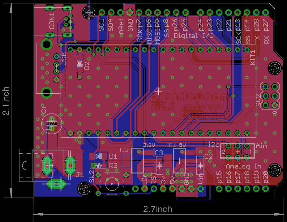
- Board photo vvv

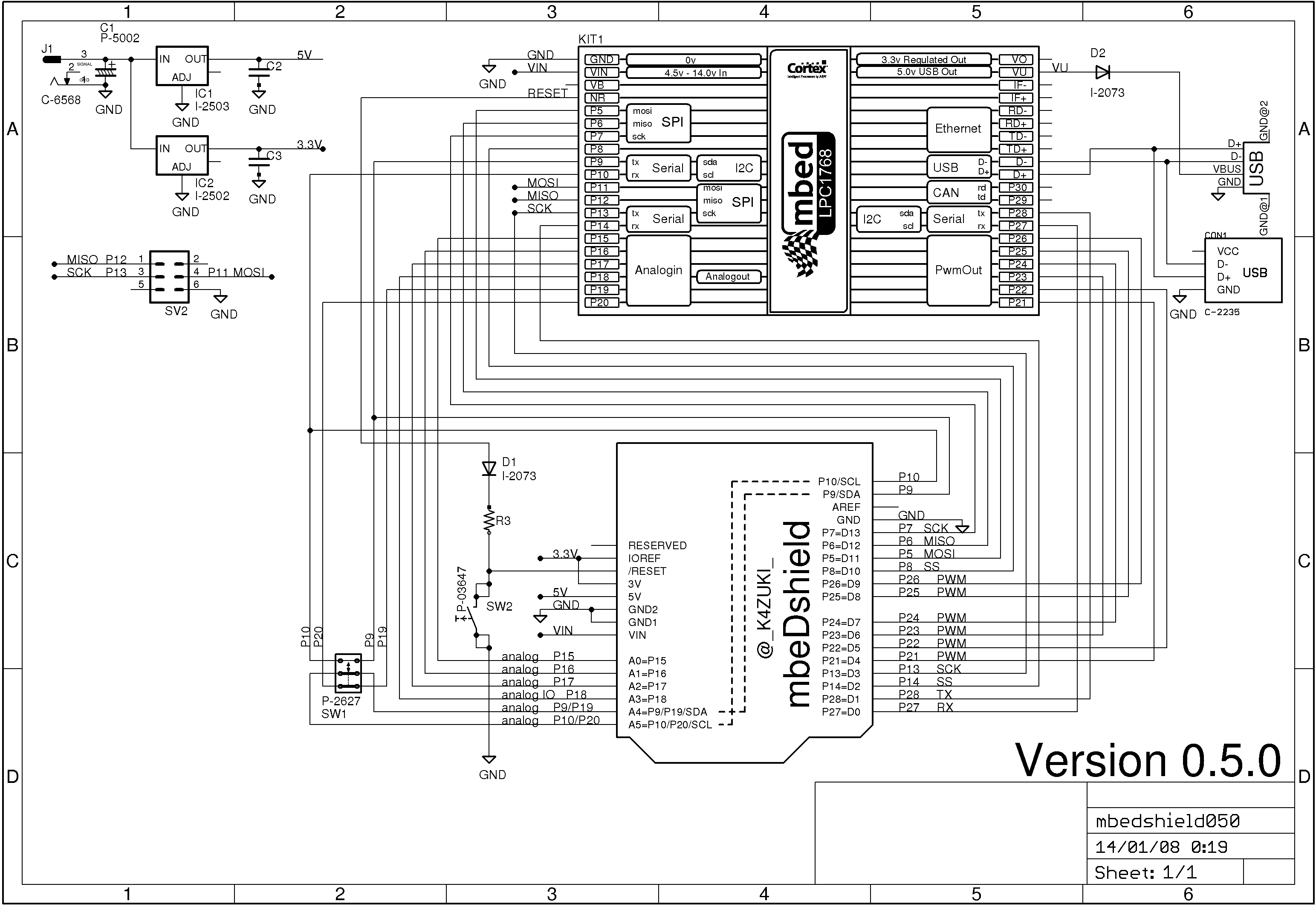
- Schematic photo vvv

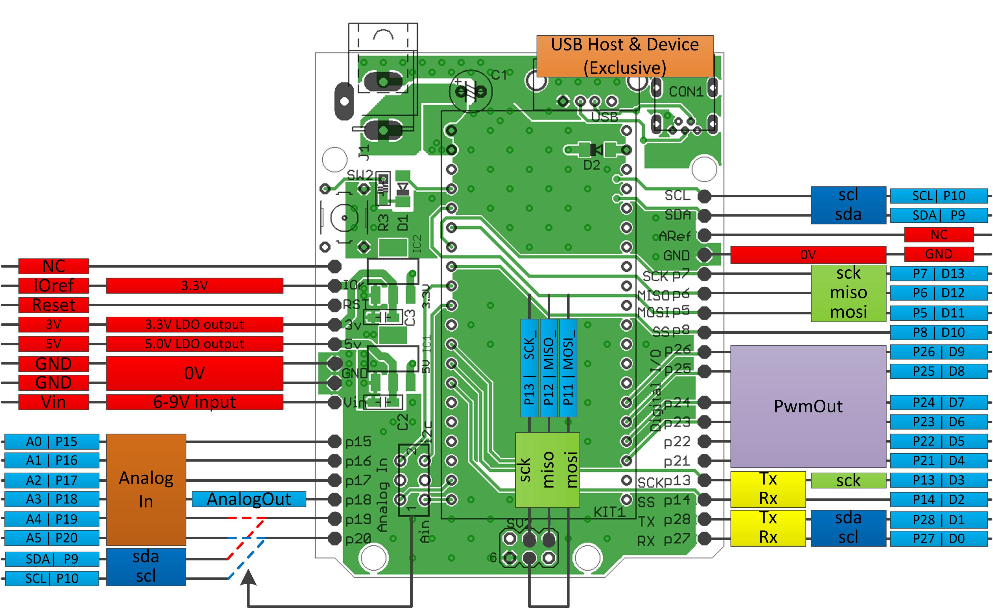
- Functionality photo vvv

Latest eagle files
PCB >> /media/uploads/k4zuki/mbedshield050.brd
SCH >> /media/uploads/k4zuki/mbedshield050.sch
BIG changes from previous version
- Ethernet RJ45 connector is removed.
- http://mbed.org/components/Seeed-Ethernet-Shield-V20/ is the biggest hint to use Ethernet!
MostALL of components can be bought at Akizuki http://akizukidenshi.com/- But sorry, they do not send parts to abroad
- Pinout is changed!
| arduino | 0.4.0 | 0.5.0 |
|---|---|---|
| D4 | p12 | p21 |
| D5 | p11 | p22 |
| MOSI_ | none | p11 |
| MISO_ | none | p12 |
| SCK_ | none | p13 |
This design has bug(s)
- I2C functional pin differs between 1768 and 11U24.
Fixed bugs here
- MiniUSB cable cannot be connected on mbed if you solder high-height electrolytic capacitor on C3.
- http://akizukidenshi.com/catalog/g/gP-05002/ is the solution to make this 100% AKIZUKI parts!
- the 6-pin ISP port is not inprimented in version 0.4.0
it will be fixed in later version 0.4.1/0.4.2/0.5.0This has beenfixed
I am doing some porting to use existing arduino shields but it may faster if you do it by yourself...
you can use arduino PinName "A0-A5,D0-D13" plus backside SPI port for easier porting.
To do this you have to edit PinName enum in
- "mbed/TARGET_LPC1768/PinNames.h" or
- "mbed/TARGET_LPC11U24/PinNames.h" as per your target mbed.
here is the actual list: This list includes define switch to switch pin assignment
part_of_PinNames.h
        USBTX = P0_2,
        USBRX = P0_3,

//from here mbeDshield mod
        D0=p27,
        D1=p28,
        D2=p14,
        D3=p13,
#ifdef MBEDSHIELD_050
        MOSI_=p11,
        MISO_=p12,
        SCK_=p13,
        D4=p21,
        D5=p22,
#else
        D4=p12,
        D5=p11,
#endif
        D6=p23,
        D7=p24,
        D8=p25,
        D9=p26,
        D10=p8,
        D11=p5,
        D12=p6,
        D13=p7,
        A0=p15,
        A1=p16,
        A2=p17,
        A3=p18,
        A4=p19,
        A5=p20,
        SDA=p9,
        SCL=p10,
//mbeDshield mod ends here
        // Not connected
        NC = (int)0xFFFFFFFF
Diff: I2C.h
- Revision:
- 20:029aa53d7323
- Parent:
- 12:f63353af7be8
- Child:
- 21:3944f1e2fa4f
diff -r e6be4cd80aad -r 029aa53d7323 I2C.h
--- a/I2C.h	Tue May 18 16:04:21 2010 +0000
+++ b/I2C.h	Thu Jun 03 11:17:50 2010 +0000
@@ -17,7 +17,7 @@
  *  An I2C Master, used for communicating with I2C slave devices
  *
  * Example:
- * > // Read from I2C slave at address 0x1234
+ * > // Read from I2C slave at address 0x62
  * >
  * > #include "mbed.h"
  * >
@@ -33,6 +33,13 @@

 public:

+    enum RxStatus {
+        NoData
+        , MasterGeneralCall
+        , MasterWrite
+        , MasterRead
+    };
+
     /* Constructor: I2C
      *  Create an I2C Master interface, connected to the specified pins
      *
@@ -60,9 +67,10 @@
      *  address - 8-bit I2C slave address [ addr | 1 ]
      *  data - Pointer to the byte-array to read data in to
      *  length - Number of bytes to read
+     *  repeated - Repeated start, true - don't send stop at end
      *  returns - 0 on success (ack), or non-0 on failure (nack)
      */
-    int read(int address, char *data, int length);
+    int read(int address, char *data, int length, bool repeated = false);

     /* Function: write
      *  Write to an I2C slave
@@ -74,17 +82,18 @@
      *  address - 8-bit I2C slave address [ addr | 0 ]
      *  data - Pointer to the byte-array data to send
      *  length - Number of bytes to send
+     *  repeated - Repeated start, true - do not send stop at end
      *  returns - 0 on success (ack), or non-0 on failure (nack)
      */
-    int write(int address, const char *data, int length);
+    int write(int address, const char *data, int length, bool repeated = false);

 protected:

-    I2CName _i2c;
-
     void aquire();
-    static I2C *_owner;
-    int _hz;
+
+    I2CName     _i2c;
+    static I2C  *_owner;
+    int         _hz;

 };
