Potentiometer
Description
This tutorial will explain the basic concepts of potentiometers and how to integrate them into your mBed projects.
Potentiometer Basics
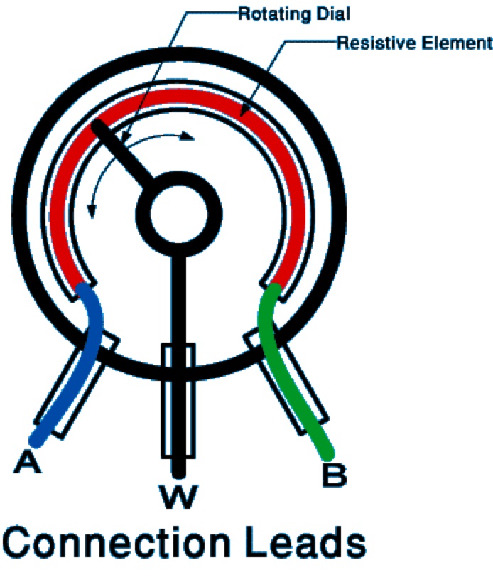
In the world of electronics, potentiometers are informally referred to as pots. The most common type of pots are three-terminal resistors with an electrical contact that either slides or rotates along a resistor (or in some cases between different resistors) in a voltage divider circuit to provide variable resistance (and variable voltage output). 
By connecting the wiper lead to an analog input, it is possible to sense the voltage drop and determine the angle of the pot. Using the AnalogIn class in the mBed API, the value can be read in as a float [0, 1.0]. This value can then be used for a wide range of applications. Some examples are servo/dc motor control, volume control, or to calibrate values within your code (ex: sampling period, or lcd refresh rate).
Demo
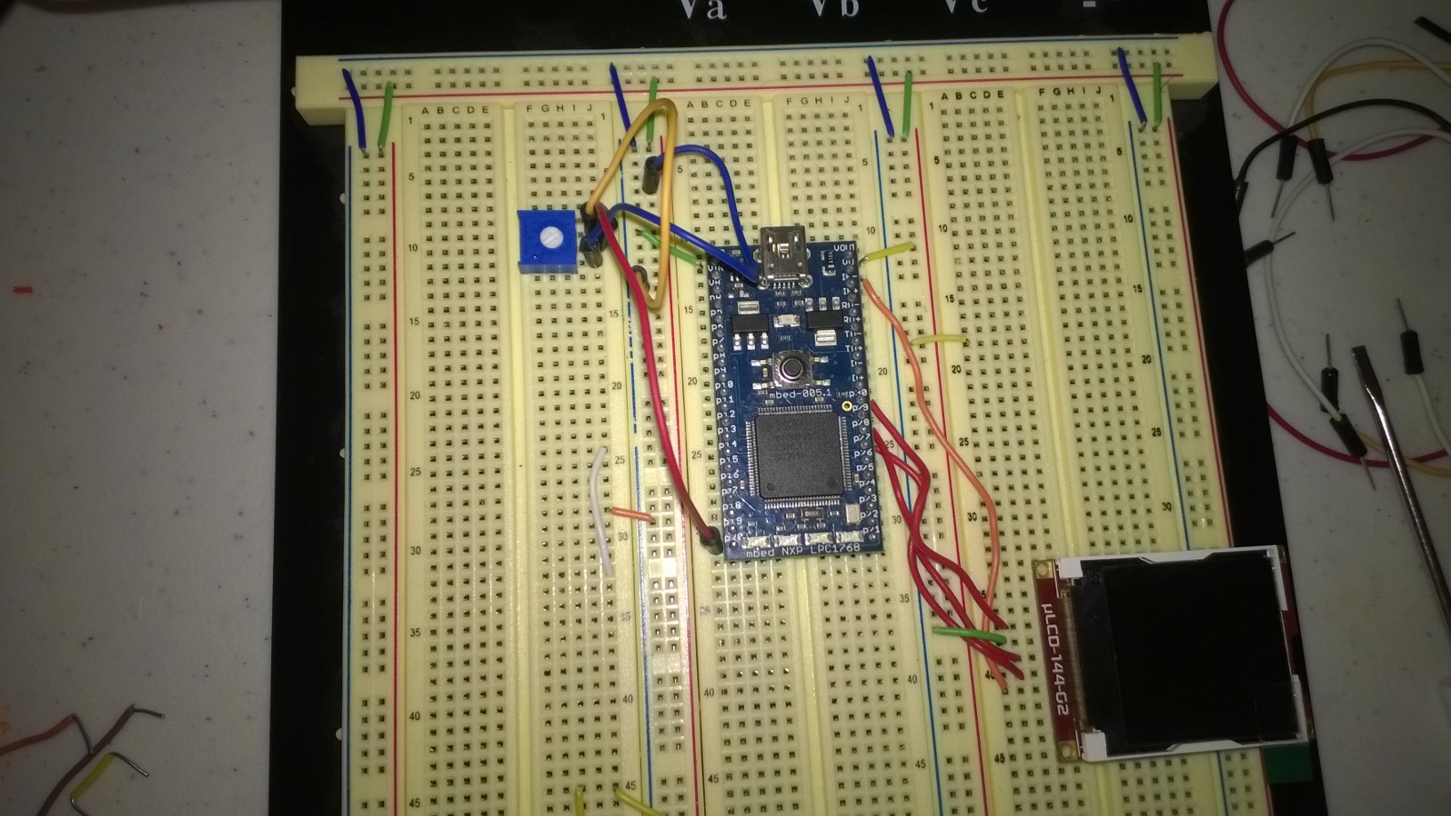
In this demo we will be using a simple potentiometer with leads that are easily connected to a breadboard and then to an analog input on the mBed. We will read the value of the potentiometer, and display the value on a bar graph on the built-in LEDs as well as the uLCD-144-G2 from 4D Systems. Visit the uLCD documentation page for hooking the lcd up to your mBed.

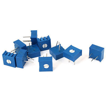
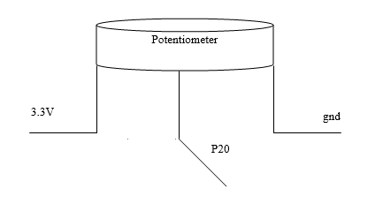
These simple pots include three leads - the outer two should be connected to 3.3v and gnd (the Vout and Gnd pins on the mBed) and the inner lead should be connected to p20 (an analog input).


Once the potentiometer is correctly hooked up to your mBed, Import, compile, and download the code to your mBed.
Import programECE4180L4_Pot
"Hello World" program for using potentiometers with mBed. ECE4180 Lab 4.
main.cpp
#include "mbed.h"
#include "uLCD_4DGL.h"


DigitalOut _led1(LED1);
DigitalOut _led2(LED2);
DigitalOut _led3(LED3);
DigitalOut _led4(LED4);
AnalogIn pot(p20);
uLCD_4DGL lcd(p28, p27, p30);

const int startX = SIZE_X / 3;
const int stopX = startX * 2;
const int stopY = SIZE_Y;
int startY = 0;
void PrintLCDGraph(float value){
    int prevY = startY;
    startY = SIZE_Y * (1 - value);
    // clear part of graph that doesn't overlap between samples
    lcd.filled_rectangle(startX, prevY, stopX, startY, BLACK);
    lcd.filled_rectangle(startX, startY, stopX, stopY, RED);
}
void PrintLEDGraph(float value){
    _led1 = (value >= 0.2) ? 1 : 0;
    _led2 = (value >= 0.4) ? 1 : 0;
    _led3 = (value >= 0.6) ? 1 : 0;
    _led4 = (value >= 0.8) ? 1 : 0;
}
int main() {
    float sample;
    while(1) {
        sample = pot;
        PrintLEDGraph(sample);
        PrintLCDGraph(sample);
        wait(0.1);
    }
}
Please log in to post comments.
