mbed API for Raspberry Pi boards.
mbedPi
This is an attempt to implement a limited number of mbed APIs for Raspberry Pi single-board computers. The project was inspired by and based on the arduPi library developed for the Arduino by Cooking Hacks .
Specifications
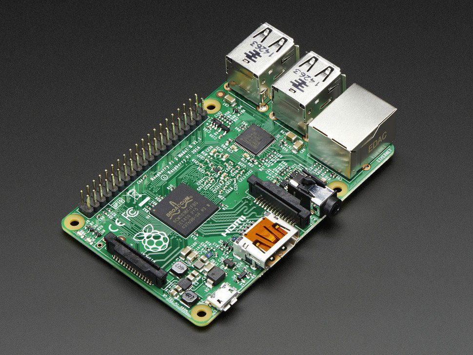
- Chip: Broadcom BCM2836 SoC
- Core architecture: Quad-core ARM Cortex-A7
- CPU frequency: 900 MHz
- GPU: Dual Core VideoCore IV® Multimedia Co-Processor
- Memory: 1GB LPDDR2
- Operating System: Boots from Micro SD card, running a version of the Linux operating system
- Power: Micro USB socket 5V, 2A
Connectors
- Ethernet: 10/100 BaseT Ethernet socket
- Video Output: HDMI (rev 1.3 & 1.4)
- Audio Output: 3.5mm jack, HDMI
- USB: 4 x USB 2.0 Connector
- GPIO Connector: 40-pin 2.54 mm (100 mil) expansion header: 2x20 strip providing 27 GPIO pins as well as +3.3 V, +5 V and GND supply lines
- Camera Connector: 15-pin MIPI Camera Serial Interface (CSI-2)
- JTAG: Not populated
- Display Connector: Display Serial Interface (DSI) 15 way flat flex cable connector with two data lanes and a clock lane
- Memory Card Slot: Micro SDIO
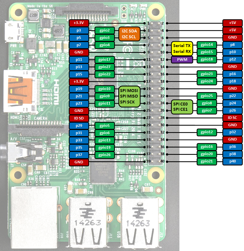
GPIO connector pinout
Information
Only the labels printed in blue/white or green/white (i.e. p3, gpio2 ...) must be used in your code. The other labels are given as information (alternate-functions, power pins, ...).
Building programs for the Raspberry Pi with mbedPi
I use Qt Creator for development, however you can use any other IDE available on the Raspberry Pi (e.g. Geany) if you like. For a quick try:
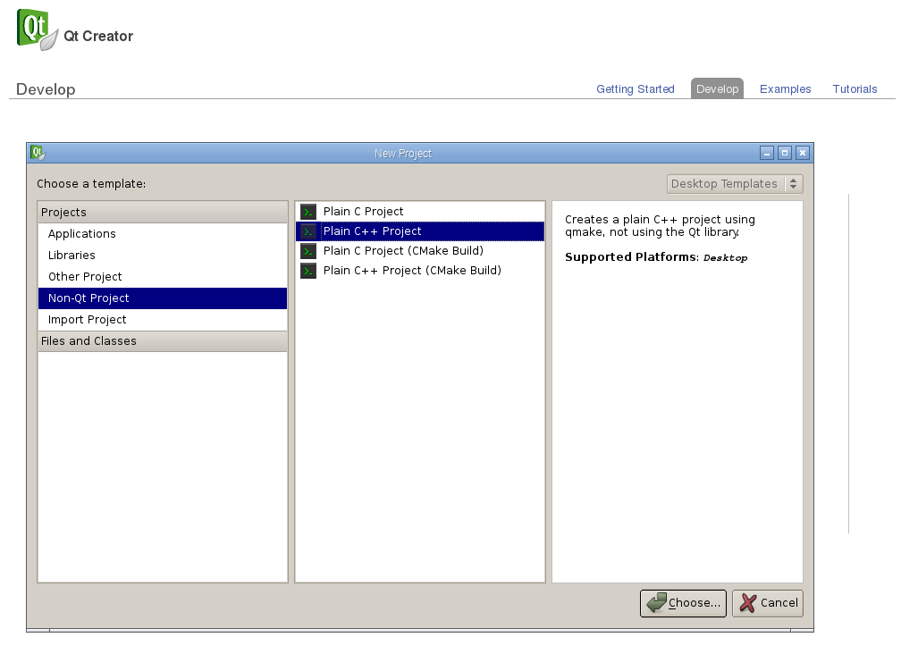
- Install Qt and the Qt Creator onto your Raspberry Pi. Then create a new "Blinky" Plain non-Qt C++ Project as follows:
- Change the main code as below:
main.cpp
#include "mbedPi.h"

int main()
{
    DigitalOut  myled(p7);

    while(1) {
        myled = 1; // LED is ON
        wait(0.2); // 200 ms
        myled = 0; // LED is OFF
        wait(1.0); // 1 sec
        printf("Blink\r\n");
    }
}
- Copy the mbedPi.zip file into your project's folder and unzip.
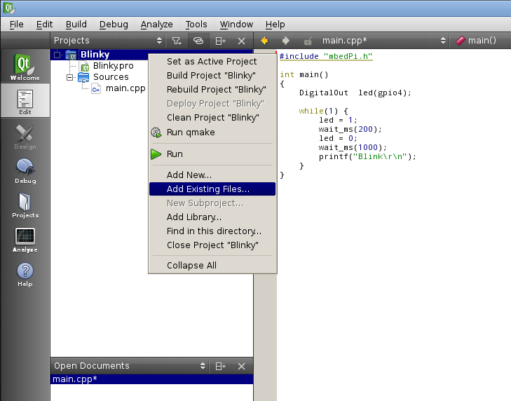
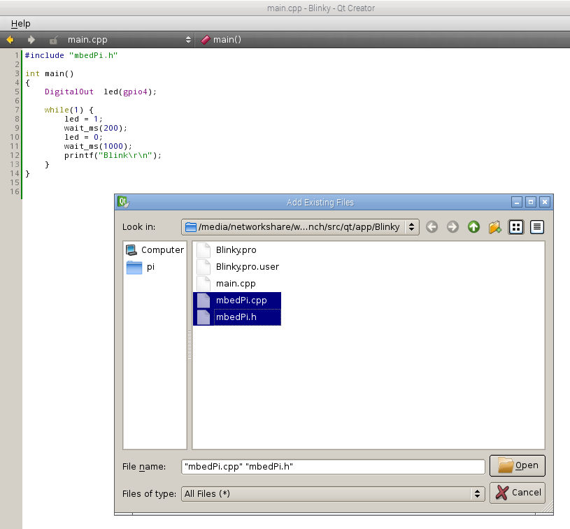
- Add the mbedPi.h and mbedPi.cpp files to your project by right clicking on the "Blinky" project and then clicking on the "Add Existing Files..." option in the local menu:
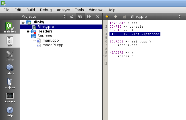
- Double click on Blinky.pro to open it for editing and add new libraries by inserting a new line as follows:
- Compile the project.
- Connect an LED through a 1k resistor to pin 7 and the ground on the Raspberry Pi GPIO connector.
- Run the binary as sudo (sudo ./Blinky) and you should see the LED blinking.

- Press Ctrl+c to stop running the application.
Diff: include/BCM2835.h
- Revision:
- 1:1f2d9982fa8c
--- /dev/null	Thu Jan 01 00:00:00 1970 +0000
+++ b/include/BCM2835.h	Tue Dec 20 12:08:07 2022 +0000
@@ -0,0 +1,433 @@
+/* bcm2835.h
+
+    C and C++ support for Broadcom BCM 2835 as used in Raspberry Pi
+
+    Author: Mike McCauley
+    Copyright (C) 2011-2013 Mike McCauley
+    $Id: bcm2835.h,v 1.26 2020/01/11 05:07:13 mikem Exp mikem $
+ */
+
+#ifndef _BCM2835_H_
+#define _BCM2835_H_
+
+/*$off*/
+#include <errno.h>
+#include <fcntl.h>
+#include <netinet/in.h>
+#include <signal.h>
+#include <stdlib.h>
+#include <stdio.h>
+#include <sys/ipc.h>
+#include <sys/sem.h>
+#include <sys/socket.h>
+#include <sys/time.h>
+#include <sys/types.h>
+#include <sys/wait.h>
+#include <sys/mman.h>
+#include <string.h>
+#include <time.h>
+#include <termios.h>
+#include <ctype.h>
+#include <sys/ioctl.h>
+#include <limits.h>
+#include <algorithm>
+#include <limits.h>
+#include <pthread.h>
+#include <poll.h>
+#include "PinNames.h"
+
+#define BCM2835_PERI_BASE       0x20000000
+#define BCM2835_PERI_SIZE       0x01000000
+
+#define BCM2835_ST_BASE			0x3000
+#define BCM2835_CLOCK_BASE      0x101000
+#define BCM2835_GPIO_PWM        0x20C000
+#define BCM2835_BSC1_BASE       0x804000
+#define BCM2835_SPI0_BASE       0x204000
+
+/* Defines for ST
+   GPIO register offsets from BCM2835_ST_BASE.
+   Offsets into the ST Peripheral block in bytes per 12.1 System Timer Registers
+   The System Timer peripheral provides four 32-bit timer channels and a single 64-bit free running counter.
+   BCM2835_ST_CLO is the System Timer Counter Lower bits register.
+   The system timer free-running counter lower register is a read-only register that returns the current value
+   of the lower 32-bits of the free running counter.
+   BCM2835_ST_CHI is the System Timer Counter Upper bits register.
+   The system timer free-running counter upper register is a read-only register that returns the current value
+   of the upper 32-bits of the free running counter.
+*/
+#define BCM2835_ST_CS 			0x0000 /*!< System Timer Control/Status */
+#define BCM2835_ST_CLO 			0x0004 /*!< System Timer Counter Lower 32 bits */
+#define BCM2835_ST_CHI 			0x0008 /*!< System Timer Counter Upper 32 bits */
+
+// Defines for I2C
+// GPIO register offsets from BCM2835_BSC*_BASE.
+// Offsets into the BSC Peripheral block in bytes per 3.1 BSC Register Map
+#define BCM2835_BSC_C           0x0000     ///< BSC Master Control
+#define BCM2835_BSC_S           0x0004     ///< BSC Master Status
+#define BCM2835_BSC_DLEN        0x0008     ///< BSC Master Data Length
+#define BCM2835_BSC_A           0x000c     ///< BSC Master Slave Address
+#define BCM2835_BSC_FIFO        0x0010     ///< BSC Master Data FIFO
+#define BCM2835_BSC_DIV         0x0014     ///< BSC Master Clock Divider
+#define BCM2835_BSC_DEL         0x0018     ///< BSC Master Data Delay
+#define BCM2835_BSC_CLKT        0x001c     ///< BSC Master Clock Stretch Timeout
+
+// Register masks for BSC_C
+#define BCM2835_BSC_C_I2CEN     0x00008000  ///< I2C Enable, 0 = disabled, 1 = enabled
+#define BCM2835_BSC_C_INTR      0x00000400  ///< Interrupt on RX
+#define BCM2835_BSC_C_INTT      0x00000200  ///< Interrupt on TX
+#define BCM2835_BSC_C_INTD      0x00000100  ///< Interrupt on DONE
+#define BCM2835_BSC_C_ST        0x00000080  ///< Start transfer, 1 = Start a new transfer
+#define BCM2835_BSC_C_CLEAR_1   0x00000020  ///< Clear FIFO Clear
+#define BCM2835_BSC_C_CLEAR_2   0x00000010  ///< Clear FIFO Clear
+#define BCM2835_BSC_C_READ      0x00000001  ///<	Read transfer
+
+// Register masks for BSC_S
+#define BCM2835_BSC_S_CLKT      0x00000200  ///< Clock stretch timeout
+#define BCM2835_BSC_S_ERR       0x00000100  ///< ACK error
+#define BCM2835_BSC_S_RXF       0x00000080  ///< RXF FIFO full, 0 = FIFO is not full, 1 = FIFO is full
+#define BCM2835_BSC_S_TXE       0x00000040  ///< TXE FIFO full, 0 = FIFO is not full, 1 = FIFO is full
+#define BCM2835_BSC_S_RXD       0x00000020  ///< RXD FIFO contains data
+#define BCM2835_BSC_S_TXD       0x00000010  ///< TXD FIFO can accept data
+#define BCM2835_BSC_S_RXR       0x00000008  ///< RXR FIFO needs reading (full)
+#define BCM2835_BSC_S_TXW       0x00000004  ///< TXW FIFO needs writing (full)
+#define BCM2835_BSC_S_DONE      0x00000002  ///< Transfer DONE
+#define BCM2835_BSC_S_TA        0x00000001  ///< Transfer Active
+#define BCM2835_BSC_FIFO_SIZE   16          ///< BSC FIFO size
+#define BCM2835_CORE_CLK_HZ     250000000   ///< 250 MHz
+
+    /// \brief bcm2835I2CClockDivider
+    /// Specifies the divider used to generate the I2C clock from the system clock.
+    /// Clock divided is based on nominal base clock rate of 250MHz
+typedef enum
+{
+    BCM2835_I2C_CLOCK_DIVIDER_2500  = 2500, ///< 2500 = 10us = 100 kHz
+    BCM2835_I2C_CLOCK_DIVIDER_626   = 626,  ///< 622 = 2.504us = 399.3610 kHz
+    BCM2835_I2C_CLOCK_DIVIDER_150   = 150,  ///< 150 = 60ns = 1.666 MHz (default at reset)
+    BCM2835_I2C_CLOCK_DIVIDER_148   = 148,  ///< 148 = 59ns = 1.689 MHz
+} bcm2835I2CClockDivider;
+
+/// \brief bcm2835I2CReasonCodes
+/// Specifies the reason codes for the bcm2835_i2c_write and bcm2835_i2c_read functions.
+typedef enum
+{
+    BCM2835_I2C_REASON_OK           = 0x00, ///< Success
+    BCM2835_I2C_REASON_ERROR_NACK   = 0x01, ///< Received a NACK
+    BCM2835_I2C_REASON_ERROR_CLKT   = 0x02, ///< Received Clock Stretch Timeout
+    BCM2835_I2C_REASON_ERROR_DATA   = 0x04, ///< Not all data is sent / received
+} bcm2835I2CReasonCodes;
+
+typedef enum
+{
+    RPI_V2_GPIO_P1_03               = 2,    ///< Version 2, Pin P1-03
+    RPI_V2_GPIO_P1_05               = 3,    ///< Version 2, Pin P1-05
+} RPiGPIOPin;
+
+#define BSC0_C        *(bsc0.addr + 0x00)
+#define BSC0_S        *(bsc0.addr + 0x01)
+#define BSC0_DLEN     *(bsc0.addr + 0x02)
+#define BSC0_A        *(bsc0.addr + 0x03)
+#define BSC0_FIFO     *(bsc0.addr + 0x04)
+
+#define BSC_C_I2CEN   (1<< 15)
+#define BSC_C_INTR    (1<< 10)
+#define BSC_C_INTT    (1<< 9)
+#define BSC_C_INTD    (1<< 8)
+#define BSC_C_ST      (1<< 7)
+#define BSC_C_CLEAR   (1<< 4)
+#define BSC_C_READ    1
+
+#define START_READ    BSC_C_I2CEN|BSC_C_ST|BSC_C_CLEAR|BSC_C_READ
+#define START_WRITE   BSC_C_I2CEN|BSC_C_ST
+
+#define BSC_S_CLKT   (1<< 9)
+#define BSC_S_ERR    (1<< 8)
+#define BSC_S_RXF    (1<< 7)
+#define BSC_S_TXE    (1<< 6)
+#define BSC_S_RXD    (1<< 5)
+#define BSC_S_TXD    (1<< 4)
+#define BSC_S_RXR    (1<< 3)
+#define BSC_S_TXW    (1<< 2)
+#define BSC_S_DONE   (1<< 1)
+#define BSC_S_TA     1
+
+#define CLEAR_STATUS    BSC_S_CLKT|BSC_S_ERR|BSC_S_DONE
+
+#define GPFSEL0     *(gpio.addr + 0)
+#define GPFSEL1     *(gpio.addr + 1)
+#define GPFSEL2     *(gpio.addr + 2)
+#define GPFSEL3     *(gpio.addr + 3)
+#define GPFSEL4     *(gpio.addr + 4)
+#define GPFSEL5     *(gpio.addr + 5)
+// Reserved @ word offset 6
+#define GPSET0      *(gpio.addr + 7)
+#define GPSET1      *(gpio.addr + 8)
+// Reserved @ word offset 9
+#define GPCLR0      *(gpio.addr + 10)
+#define GPCLR1      *(gpio.addr + 11)
+// Reserved @ word offset 12
+#define GPLEV0      *(gpio.addr + 13)
+#define GPLEV1      *(gpio.addr + 14)
+
+#define PAGESIZE    4096
+#define BLOCK_SIZE  4096
+
+/// Defines for SPI
+/// GPIO register offsets from BCM2835_SPI0_BASE.
+/// Offsets into the SPI Peripheral block in bytes per 10.5 SPI Register Map
+#define BCM2835_SPI0_CS                      0x0000 ///< SPI Master Control and Status
+#define BCM2835_SPI0_FIFO                    0x0004 ///< SPI Master TX and RX FIFOs
+#define BCM2835_SPI0_CLK                     0x0008 ///< SPI Master Clock Divider
+#define BCM2835_SPI0_DLEN                    0x000c ///< SPI Master Data Length
+#define BCM2835_SPI0_LTOH                    0x0010 ///< SPI LOSSI mode TOH
+#define BCM2835_SPI0_DC                      0x0014 ///< SPI DMA DREQ Controls
+
+// Register masks for SPI0_CS
+#define BCM2835_SPI0_CS_LEN_LONG             0x02000000 ///< Enable Long data word in Lossi mode if DMA_LEN is set
+#define BCM2835_SPI0_CS_DMA_LEN              0x01000000 ///< Enable DMA mode in Lossi mode
+#define BCM2835_SPI0_CS_CSPOL2               0x00800000 ///< Chip Select 2 Polarity
+#define BCM2835_SPI0_CS_CSPOL1               0x00400000 ///< Chip Select 1 Polarity
+#define BCM2835_SPI0_CS_CSPOL0               0x00200000 ///< Chip Select 0 Polarity
+#define BCM2835_SPI0_CS_RXF                  0x00100000 ///< RXF - RX FIFO Full
+#define BCM2835_SPI0_CS_RXR                  0x00080000 ///< RXR RX FIFO needs Reading ( full)
+#define BCM2835_SPI0_CS_TXD                  0x00040000 ///< TXD TX FIFO can accept Data
+#define BCM2835_SPI0_CS_RXD                  0x00020000 ///< RXD RX FIFO contains Data
+#define BCM2835_SPI0_CS_DONE                 0x00010000 ///< Done transfer Done
+#define BCM2835_SPI0_CS_TE_EN                0x00008000 ///< Unused
+#define BCM2835_SPI0_CS_LMONO                0x00004000 ///< Unused
+#define BCM2835_SPI0_CS_LEN                  0x00002000 ///< LEN LoSSI enable
+#define BCM2835_SPI0_CS_REN                  0x00001000 ///< REN Read Enable
+#define BCM2835_SPI0_CS_ADCS                 0x00000800 ///< ADCS Automatically Deassert Chip Select
+#define BCM2835_SPI0_CS_INTR                 0x00000400 ///< INTR Interrupt on RXR
+#define BCM2835_SPI0_CS_INTD                 0x00000200 ///< INTD Interrupt on Done
+#define BCM2835_SPI0_CS_DMAEN                0x00000100 ///< DMAEN DMA Enable
+#define BCM2835_SPI0_CS_TA                   0x00000080 ///< Transfer Active
+#define BCM2835_SPI0_CS_CSPOL                0x00000040 ///< Chip Select Polarity
+#define BCM2835_SPI0_CS_CLEAR                0x00000030 ///< Clear FIFO Clear RX and TX
+#define BCM2835_SPI0_CS_CLEAR_RX             0x00000020 ///< Clear FIFO Clear RX
+#define BCM2835_SPI0_CS_CLEAR_TX             0x00000010 ///< Clear FIFO Clear TX
+#define BCM2835_SPI0_CS_CPOL                 0x00000008 ///< Clock Polarity
+#define BCM2835_SPI0_CS_CPHA                 0x00000004 ///< Clock Phase
+#define BCM2835_SPI0_CS_CS                   0x00000003 ///< Chip Select
+
+#define BCM2835_GPFSEL0                      0x0000 ///< GPIO Function Select 0
+
+#define BCM2835_GPEDS0                       0x0040 ///< GPIO Pin Event Detect Status 0
+#define BCM2835_GPREN0                       0x004c ///< GPIO Pin Rising Edge Detect Enable 0
+#define BCM2835_GPFEN0                       0x0048 ///< GPIO Pin Falling Edge Detect Enable 0
+#define BCM2835_GPHEN0                       0x0064 ///< GPIO Pin High Detect Enable 0
+#define BCM2835_GPLEN0                       0x0070 ///< GPIO Pin Low Detect Enable 0
+
+/* Defines for PWM, word offsets (ie 4 byte multiples) */
+#define BCM2835_PWM_CONTROL 0
+#define BCM2835_PWM_STATUS  1
+#define BCM2835_PWM_DMAC    2
+#define BCM2835_PWM0_RANGE  4
+#define BCM2835_PWM0_DATA   5
+#define BCM2835_PWM_FIF1    6
+#define BCM2835_PWM1_RANGE  8
+#define BCM2835_PWM1_DATA   9
+
+/* Defines for PWM Clock, word offsets (ie 4 byte multiples) */
+#define BCM2835_PWMCLK_CNTL     40
+#define BCM2835_PWMCLK_DIV      41
+#define BCM2835_PWM_PASSWRD     (0x5A << 24)  /*!< Password to enable setting PWM clock */
+
+#define BCM2835_PWM1_MS_MODE    0x8000  /*!< Run in Mark/Space mode */
+#define BCM2835_PWM1_USEFIFO    0x2000  /*!< Data from FIFO */
+#define BCM2835_PWM1_REVPOLAR   0x1000  /*!< Reverse polarity */
+#define BCM2835_PWM1_OFFSTATE   0x0800  /*!< Ouput Off state */
+#define BCM2835_PWM1_REPEATFF   0x0400  /*!< Repeat last value if FIFO empty */
+#define BCM2835_PWM1_SERIAL     0x0200  /*!< Run in serial mode */
+#define BCM2835_PWM1_ENABLE     0x0100  /*!< Channel Enable */
+
+#define BCM2835_PWM0_MS_MODE    0x0080  /*!< Run in Mark/Space mode */
+#define BCM2835_PWM_CLEAR_FIFO  0x0040  /*!< Clear FIFO */
+#define BCM2835_PWM0_USEFIFO    0x0020  /*!< Data from FIFO */
+#define BCM2835_PWM0_REVPOLAR   0x0010  /*!< Reverse polarity */
+#define BCM2835_PWM0_OFFSTATE   0x0008  /*!< Ouput Off state */
+#define BCM2835_PWM0_REPEATFF   0x0004  /*!< Repeat last value if FIFO empty */
+#define BCM2835_PWM0_SERIAL     0x0002  /*!< Run in serial mode */
+#define BCM2835_PWM0_ENABLE     0x0001  /*!< Channel Enable */
+
+#define PWM_CHANNEL             0
+
+/// \brief bcm2835SPIBitOrder
+/// Specifies the SPI data bit ordering
+typedef enum
+{
+    LSBFIRST = 0,  ///< LSB First
+    MSBFIRST = 1///< MSB First
+} bcm2835SPIBitOrder;
+
+/// \brief bcm2835SPIMode
+/// Specify the SPI data mode
+typedef enum
+{
+    SPI_MODE0 = 0,  ///< CPOL = 0, CPHA = 0
+    SPI_MODE1 = 1,  ///< CPOL = 0, CPHA = 1
+    SPI_MODE2 = 2,  ///< CPOL = 1, CPHA = 0
+    SPI_MODE3 = 3,  ///< CPOL = 1, CPHA = 1
+} bcm2835SPIMode;
+
+/// \brief bcm2835SPIChipSelect
+/// Specify the SPI chip select pin(s)
+typedef enum
+{
+    SPI_CS0 = 0,     ///< Chip Select 0
+    SPI_CS1 = 1,     ///< Chip Select 1
+    SPI_CS2 = 2,     ///< Chip Select 2 (ie pins CS1 and CS2 are asserted)
+    SPI_CS_NONE = 3, ///< No CS, control it yourself
+} bcm2835SPIChipSelect;
+
+/// \brief bcm2835SPIClockDivider
+/// Specifies the divider used to generate the SPI clock from the system clock.
+/// Figures below give the divider, clock period and clock frequency.
+typedef enum
+{
+    SPI_CLOCK_DIV65536 = 0,       ///< 65536 = 256us = 4kHz
+    SPI_CLOCK_DIV32768 = 32768,   ///< 32768 = 126us = 8kHz
+    SPI_CLOCK_DIV16384 = 16384,   ///< 16384 = 64us = 15.625kHz
+    SPI_CLOCK_DIV8192  = 8192,    ///< 8192 = 32us = 31.25kHz
+    SPI_CLOCK_DIV4096  = 4096,    ///< 4096 = 16us = 62.5kHz
+    SPI_CLOCK_DIV2048  = 2048,    ///< 2048 = 8us = 125kHz
+    SPI_CLOCK_DIV1024  = 1024,    ///< 1024 = 4us = 250kHz
+    SPI_CLOCK_DIV512   = 512,     ///< 512 = 2us = 500kHz
+    SPI_CLOCK_DIV256   = 256,     ///< 256 = 1us = 1MHz
+    SPI_CLOCK_DIV128   = 128,     ///< 128 = 500ns = = 2MHz
+    SPI_CLOCK_DIV64    = 64,      ///< 64 = 250ns = 4MHz
+    SPI_CLOCK_DIV32    = 32,      ///< 32 = 125ns = 8MHz
+    SPI_CLOCK_DIV16    = 16,      ///< 16 = 50ns = 20MHz
+    SPI_CLOCK_DIV8     = 8,       ///< 8 = 25ns = 40MHz
+    SPI_CLOCK_DIV4     = 4,       ///< 4 = 12.5ns 80MHz
+    SPI_CLOCK_DIV2     = 2,       ///< 2 = 6.25ns = 160MHz
+    SPI_CLOCK_DIV1     = 1,       ///< 0 = 256us = 4kHz
+} bcm2835SPIClockDivider;
+
+/*! \brief bcm2835PWMClockDivider
+  Specifies the divider used to generate the PWM clock from the system clock.
+  Figures below give the divider, clock period and clock frequency.
+  Clock divided is based on nominal PWM base clock rate of 19.2MHz
+  The frequencies shown for each divider have been confirmed by measurement
+*/
+typedef enum
+{
+    BCM2835_PWM_CLOCK_DIVIDER_4096  = 4096,    /*!< 4096 = 4.6875kHz */
+    BCM2835_PWM_CLOCK_DIVIDER_2048  = 2048,    /*!< 2048 = 9.375kHz */
+    BCM2835_PWM_CLOCK_DIVIDER_1024  = 1024,    /*!< 1024 = 18.75kHz */
+    BCM2835_PWM_CLOCK_DIVIDER_512   = 512,     /*!< 512 = 37.5kHz */
+    BCM2835_PWM_CLOCK_DIVIDER_256   = 256,     /*!< 256 = 75kHz */
+    BCM2835_PWM_CLOCK_DIVIDER_128   = 128,     /*!< 128 = 150kHz */
+    BCM2835_PWM_CLOCK_DIVIDER_64    = 64,      /*!< 64 = 300kHz */
+    BCM2835_PWM_CLOCK_DIVIDER_32    = 32,      /*!< 32 = 600.0kHz */
+    BCM2835_PWM_CLOCK_DIVIDER_16    = 16,      /*!< 16 = 1.2MHz */
+    BCM2835_PWM_CLOCK_DIVIDER_8     = 8,       /*!< 8 = 2.4MHz */
+    BCM2835_PWM_CLOCK_DIVIDER_4     = 4,       /*!< 4 = 4.8MHz */
+    BCM2835_PWM_CLOCK_DIVIDER_2     = 2,       /*!< 2 = 9.6MHz, fastest you can get */
+    BCM2835_PWM_CLOCK_DIVIDER_1     = 1        /*!< 1 = 4.6875kHz, same as divider 4096 */
+} bcm2835PWMClockDivider;
+
+/*! \brief bcm2835PWMClockDivider
+  Specifies the divider used to generate the PWM clock from the system clock.
+  Figures below give the divider, clock period and clock frequency.
+  Clock divided is based on nominal PWM base clock rate of 19.2MHz
+  The frequencies shown for each divider have been confirmed by measurement
+*/
+typedef enum
+{
+    BCM2835_PWM_PERIOD_212_US  = 4096,    /*!< 213.33 us  = 4.6875kHz */
+    BCM2835_PWM_PERIOD_107_US  = 2048,    /*!< 106.66 us  = 9.375kHz  */
+    BCM2835_PWM_PERIOD_53_US   = 1024,    /*!<  53.33 us  = 18.75kHz  */
+    BCM2835_PWM_PERIOD_27_US   =  512,    /*!<  26.66 us  = 37.5kHz   */
+    BCM2835_PWM_PERIOD_13_US   =  256,    /*!<  13.33 us  = 75kHz     */
+    BCM2835_PWM_PERIOD_6_6_US  =  128,    /*!<   6.66 us  = 150kHz    */
+    BCM2835_PWM_PERIOD_3_3_US  =   64,    /*!<   3.33 us  = 300kHz    */
+    BCM2835_PWM_PERIOD_1_7_US  =   32,    /*!<   1.66 us  = 600.0kHz  */
+    BCM2835_PWM_PERIOD_833_NS  =   16,    /*!< 833.33 ns  = 1.2MHz    */
+    BCM2835_PWM_PERIOD_417_NS  =    8,    /*!< 416.66 ns  = 2.4MHz    */
+    BCM2835_PWM_PERIOD_208_NS  =    4,    /*!< 208.33 ns  = 4.8MHz    */
+    BCM2835_PWM_PERIOD_104_NS  =    2,    /*!< 104.16 ns  = 9.6MHz,   */
+} bcm2835_PWM_PulsePeriod;
+
+typedef enum
+{
+    BCM2835_GPIO_FSEL_INPT  = 0b000,   ///< Input
+    BCM2835_GPIO_FSEL_OUTP  = 0b001,   ///< Output
+    BCM2835_GPIO_FSEL_ALT0  = 0b100,   ///< Alternate function 0
+    BCM2835_GPIO_FSEL_ALT1  = 0b101,   ///< Alternate function 1
+    BCM2835_GPIO_FSEL_ALT2  = 0b110,   ///< Alternate function 2
+    BCM2835_GPIO_FSEL_ALT3  = 0b111,   ///< Alternate function 3
+    BCM2835_GPIO_FSEL_ALT4  = 0b011,   ///< Alternate function 4
+    BCM2835_GPIO_FSEL_ALT5  = 0b010,   ///< Alternate function 5
+    BCM2835_GPIO_FSEL_MASK  = 0b111    ///< Function select bits mask
+} bcm2835FunctionSelect;
+
+namespace unistd {
+    //All functions of unistd.h must be called like this: unistd::the_function()
+    #include <unistd.h>
+}
+
+enum Representation{
+    BIN,
+    OCT,
+    DEC,
+    HEX,
+    BYTE
+};
+
+typedef enum {
+    LOW     = 0,
+    HIGH    = 1,
+    RISING  = 2,
+    FALLING = 3,
+    BOTH    = 4
+} Digivalue;
+//
+/*$on*/
+//
+typedef bool boolean;
+typedef unsigned char   byte;
+
+struct bcm2835_peripheral
+{
+    unsigned long           addr_p;
+    int                     mem_fd;
+    void*                   map;
+    volatile unsigned int*  addr;
+};
+
+
+
+/* Helper functions */
+int         getBoardRev();
+uint32_t*   mapmem(const char* msg, size_t size, int fd, off_t off);
+void        setBoardRev(int rev);
+pthread_t*  getThreadIdFromPin(int pin);
+void*       threadFunction(void* args);
+uint32_t    bcm2835_peri_read(volatile uint32_t* paddr);
+uint32_t    bcm2835_peri_read_nb(volatile uint32_t* paddr);
+void        bcm2835_peri_write(volatile uint32_t* paddr, uint32_t value);
+void        bcm2835_peri_write_nb(volatile uint32_t* paddr, uint32_t value);
+void        bcm2835_peri_set_bits(volatile uint32_t* paddr, uint32_t value, uint32_t mask);
+void        bcm2835_gpio_fsel(uint8_t pin, uint8_t mode);
+uint64_t    bcm2835_systimer_read(void);
+void        bcm2835_delay (unsigned int millis);
+void        bcm2835_pwm_set_clock(uint32_t divisor);
+void        bcm2835_pwm_set_mode(uint8_t channel, uint8_t markspace, uint8_t enabled);
+void        bcm2835_pwm_set_range(uint8_t channel, uint32_t range);
+void        bcm2835_pwm_set_data(uint8_t channel, uint32_t data);
+void        gpio_dir(PinName pin, PinDirection direction);
+void        gpio_mode(PinName pin, PinMode mode);
+void        gpio_write(PinName pin, int value);
+int         gpio_read(PinName pin);
+uint8_t     shiftIn(PinName dPin, PinName cPin, bcm2835SPIBitOrder order);
+void        shiftOut(PinName dPin, PinName cPin, bcm2835SPIBitOrder order, uint8_t val);
+void        attachInterrupt(PinName p, void (*f) (), Digivalue m);
+void        detachInterrupt(PinName p);
+
+typedef void (*FunctionPointer) ();
+
+static int REV = 0;
+
+#endif	// _BCM2835_H_
+
