Important changes to repositories hosted on mbed.com
Mbed hosted mercurial repositories are deprecated and are due to be permanently deleted in July 2026.
To keep a copy of this software download the repository Zip archive or clone locally using Mercurial.
It is also possible to export all your personal repositories from the account settings page.
Dependencies: mbed-MapleMini mbed
You are viewing an older revision! See the latest version
Homepage
Using Maple Mini board with mbed
Sparkfun used to sell a board (now available on eBay and from other on-line sellers for less than $4) which provides an affordable and flexible way for users to try out new ideas and build prototypes. The board is equipped with an STM32F103CBT6 microcontroller compatible with the mbed NUCLEO-F103RB platform.
Microcontroller features
- STM32F103CBT6 in LQFP48 package
- ARM®32-bit Cortex®-M3 CPU
- 72 MHz max CPU frequency
- VDD from 2.0 V to 3.6 V
- 128 KB Flash
- 20 KB SRAM
- GPIO (34) with external interrupt capability
- 12-bit ADC (2) with 10 channels
- RTC
- Timers (4)
- I2C (2)
- USART (3)
- SPI (2)
- USB 2.0 full-speed
- CAN
Board features
- Small foot-print
- Flexible board power supply: USB VBUS or external source (3.3V, 5V)
- User LED: LED1
- Two push buttons: RESET, USER BUTTON
- Mini-B USB connector
Maple Mini board pinout
Courtesy of Wim Huiskamp
 Zoom in
Information
Only the labels printed in blue/white or green/white (i.e. PB_8, PC_13, D15, A0 ...) must be used in your code. The other labels are given as information (alternate-functions, power pins, ...). You can also use these additional pin names:
LED1=PB_1   SERIAL_TX=PA_2  I2C_SCL=PB_6  SPI_MOSI=PA_7  PWM_OUT=PB_3
            SERIAL_RX=PA_3  I2C_SDA=PB_7  SPI_MISO=PA_6
                                          SPI_SCK =PA_5
                                          SPI_CS  =PB_6
Schematic
Click here to see the schematic.
Using the mbed on-line compiler to build programs for Maple Mini
- Create a program as if it was for a NUCLEO-F103RB board (select NUCLEO-F103RB as target platform in the on-line compiler).
Or click here to import this demo into your on-line compiler (then you can skip the following two steps).
- Import the mbed-MapleMini library into your project.
- Add
#include "MapleMini.h"to main.cpp before#include "mbed.h"(the position matters!).
Blinking on-board LED:
#include "MapleMini.h"
#include "mbed.h"

Serial      pc(PA_2, PA_3);
DigitalOut  myled(LED1);

int main() {
    while(1) {
        myled = 1;      // turn the LED on
        wait(0.2);      // 200 ms
        myled = 0;      // turn the LED off
        wait(1.0);      // 1 sec
        pc.printf("Blink\r\n");
    }
}
Information
If you would like to build a USB serial device with the Maple mini board then have a look at here.
Programming the Maple mini board
You can use the NUCLEO virtual disk to program the Maple Mini (drag and drop programming). To do that, an additional NUCLEO board is needed (any type equipped with ST-LINK/V2-1 will do).
- Remove the two jumpers from the CN2 connector as illustrated in Figure 8:
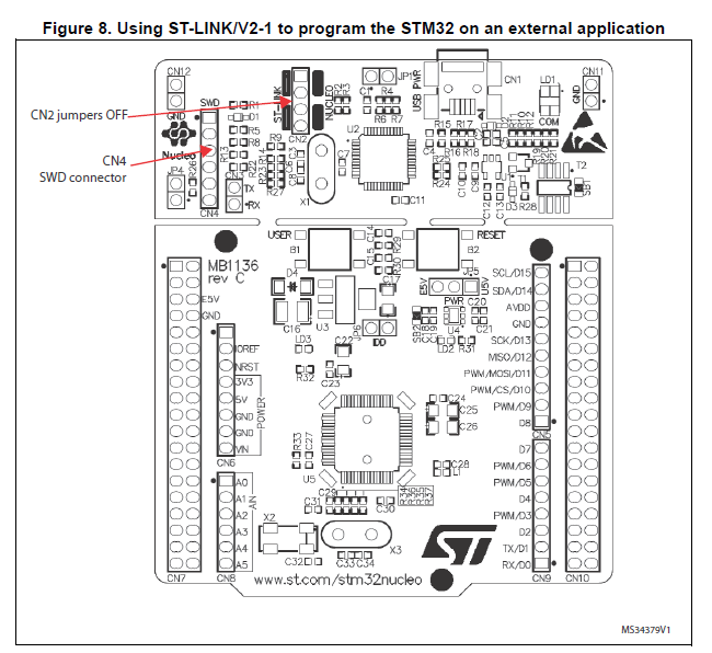
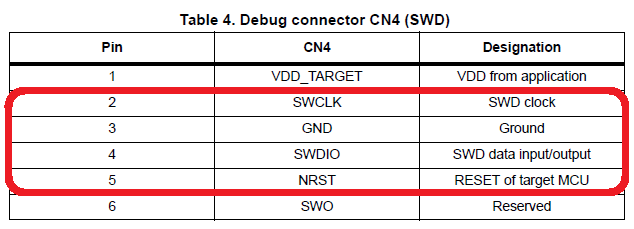
- Connect the NUCLEO board CN4 debug connector to the Maple Mini board using flying wires as follows:
| NUCLEO board CN4 connector | Maple mini board | |||
|---|---|---|---|---|
| SWCLK | <=> | SWCLK (PA_14) | ||
| GND | <=> | GND | ||
| SWDIO | <=> | SWDIO (PA_13) | ||
| NRST | <=> | RESET |
- Provide power for the Maple Mini board.
- Connect the NUCLEO board to your PC using a USB cable.
- Maple's flash memory is protected. In order to start downloading programs to the board the protection have to be removed. To do so, you need to install the STM32 ST-LINK Utility onto your computer. Once installed and running, in Target->Settings switch to Hot Plug mode.
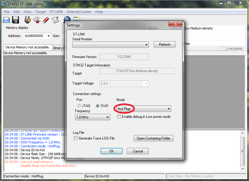
- Then go to Target->Option bytes and disable the Read Out Protection and turn the Flash Sectors Protection off as well.
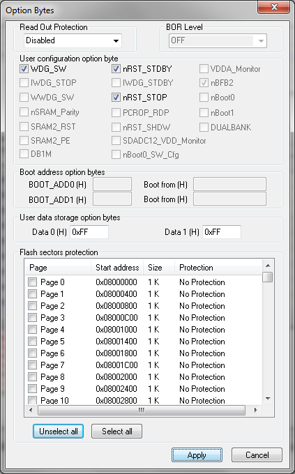
- After that you are able to fully erase the chip.
Warning! Once the chip is erased the board cannot be used with LeafLabs Maple any more!
- Exit the STM32 ST-LINK Utility. From now on, you are able to download programs to the board.
- To program the Maple Mini board, click on the Compile button and save the binary to the NUCLEO virtual disk .
For more details have a look at the User Manual, chapter 6.2.4 Using ST-LINK/V2-1 to program and debug an external STM32 application.
Using serial port (for debugging)
- Connect an FTDI or similar USB-Serial converter to your PC and to an on-board serial port (for example PA_2, PA_3). Make sure you connect the on-board TX pin to the converter's RX pin and the on-board RX pin to the converter's TX pin.
- In your code, create a
Serialobject (using TX and RX pin names of the connected serial port).
- Use
printffunction to send serial messages to the connected PC.
Sending debug messages over the ST-Link virtual com port
In case you would like to spare the external USB-Serial converter for other purposes then there is available an alternative solution proposed by X M (bitman). You can use the ST-Link virtual com port also for debugging of programs running on the Maple Mini board. However, that will require a soldering iron (and probably some soldering skills). According to the User Manual, chapter 6.8 "USART communication", solder bridges (on the back side of the NUCLEO board) SB62 and SB63 should be ON, SB13 and SB14 should be OFF. In such case it is possible to connect another USART to the NUCLEO (ST-Link) CN3 connector using flying wires. For instance on STM32F103C8T6 board it is possible to use USART2 available on PA_2 (TX) and PA_3 (RX). Two flying wires shall be connected as follows:
| Maple Mini board, pin PA_2 (Serial2 TX) | <=> | NUCLEO board CN3 connector, pin RX |
| Maple Mini board, pin PA_3 (Serial2 RX) | <=> | NUCLEO board CN3 connector, pin TX |
A smart trick proposed by Nothing Special makes even soldering needless.
The point is to redirect the UART on the NUCLEO board by software (without modifying the solder bridges on the back side of the NUCLEO board) and convert it into a "Debugger". On the NUCLEO board that you are going to use as programmer/ debugger, choose any Serial port other than Serial2 (other than the default port used for standard UART) to be initialized as standard UART. In the program below (using NUCLEO-F103RB as programmer/debugger) Serial1 (PA_9, PA_10) was selected.
Debugger
#include "mbed.h"

// declarations needed to change the parameters of stdio UART
extern serial_t     stdio_uart;
extern int          stdio_uart_inited;

int main() {
    serial_init(&stdio_uart, PA_9, PA_10); // other than Serial2
    stdio_uart_inited = 1;
    printf("Ready for debugging\r\n");
}
Once compiled (remember to select the NUCLEO board used for programing/debugging as target for the on-line compiler), download the "Debugger" program to the NUCLEO board. Please make sure you have the two jumpers in place on the CN2 connector when programming the NUCLEO board. Once downloaded to the NUCLEO board, remove the two jumpers again.
Off-line compilation and debugging with CooCox CoIDE
- Keep the NUCLEO board ( ST-LINK) connected to the Maple Mini board as in the set-up for on-line programming.
- Export your program from the mbed on-line compiler to CooCox CoIDE.

- Save the file into a folder on you PC's hard drive and unzip.
- Run CoIDE and open the project.
- To setup the debugger, open the Debugger tab and use the following settings:
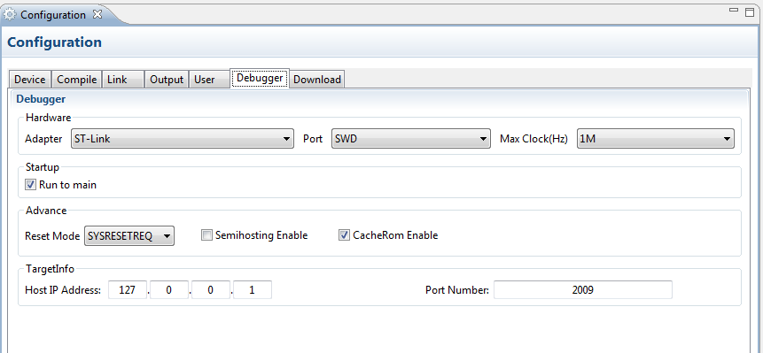
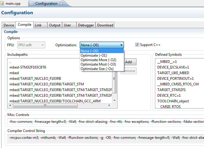
- To ensure that the execution of instructions during debugging is performed in the foreseen sequence, go to the Compile tab and select None (-O0) optimization.
- Open main.cpp for editing and rebuild the project by clicking on the Rebuild button.
- Reprogram the board by clicking on the Download Code To Flash button.
NOTE: Any time you launch the debugger the program is getting recompiled and the board reprogrammed. So you can skip this step. I included it just to illustrate how easily you can (re)program the board off-line.
- Set up some debug points and launch the debugger by clicking on the Start Debug button.
- You can execute the instructions step by step (or run to the next debug point) and observe the variables and outputs to see whether they are changing as expected...
Happy coding and debugging.