Library for communication with the HX711 24-Bit Analog-to-Digital converter.
Library for communication with the HX711 24-Bit Analog-to-Digital converter.
HX711

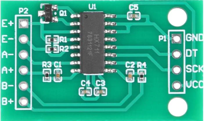
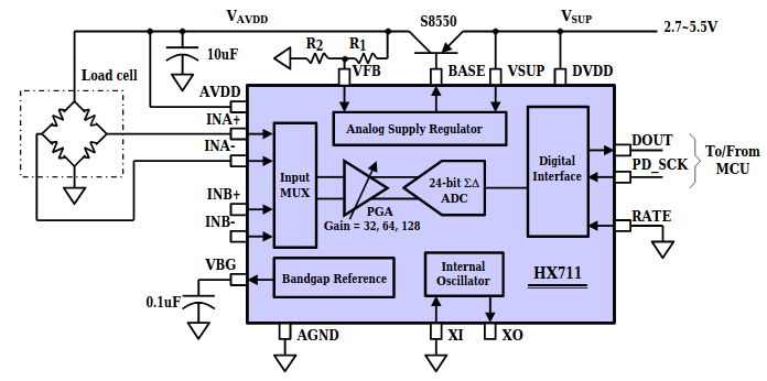
HX711 is a precision 24-bit analog-to-digital converter (ADC) designed for weigh scales and industrial control applications to interface directly with a bridge sensor. The input multiplexer selects either Channel A or B differential input to the low-noise programmable gain amplifier (PGA). Channel A can be programmed with a gain of 128 or 64, corresponding to a full-scale differential input voltage of ±20mV or ±40mV respectively, when a 5V supply is connected to AVDD analog power supply pin. Channel B has a fixed gain of 32. On-chip power supply regulator eliminates the need for an external supply regulator to provide analog power for the ADC and the sensor. Clock input is flexible. It can be from an external clock source, a crystal, or the on-chip oscillator that does not require any external component. On-chip power-on-reset circuitry simplifies digital interface initialization.

Example program:
Import programHMC1501_Hello
Example program for the HMC1501 magnetic 90° angle sensor connected to a HX711 high precision 24-bit programmable analog-to-digital converter (ADC) .
HX711.h
- Committer:
- hudakz
- Date:
- 2020-09-19
- Revision:
- 0:72a9d7812a33
File content as of revision 0:72a9d7812a33:
/*
 * Copyright (c) 2020 Zoltan Hudak <hudakz@outlook.com>
 * All rights reserved.
 *
 * This program is free software: you can redistribute it and/or modify
 * it under the terms of the GNU General Public License as published by
 * the Free Software Foundation, either version 3 of the License, or
 * (at your option) any later version.
 *
 * This program is distributed in the hope that it will be useful,
 * but WITHOUT ANY WARRANTY; without even the implied warranty of
 * MERCHANTABILITY or FITNESS FOR A PARTICULAR PURPOSE.  See the
 * GNU General Public License for more details.
 *
 * You should have received a copy of the GNU General Public License
 * along with this program.  If not, see <http://www.gnu.org/licenses/>.
 */

#ifndef _HX711_H_
#define _HX711_H_
#include "mbed.h"

/**
 * Class for communication with the HX711 24-Bit Analog-to-Digital converter (ADC)
 * (Developed for Weigh Scales by AVIA Semiconductor.)
 * This library is based on the library at https://github.com/bogde/HX711
 */
class   HX711
{
public:
    /**
     * Creates an HX711 object
     * @param avdd Analog power supply voltage [V]
     * @param sck PinName of the clock pin (digital output)
     * @param dout PinName of the data pin (digital input)
     * @param drift Chip's input offset drift [V]
     * @param gain Channel selection is made by passing the associated gain:
     *      128 or 64 for channel A, 32 for channel B
     */
    HX711(float avdd, PinName sck, PinName dout, uint8_t gain, float drift = 0) :
    _avdd(avdd),
    _sck(sck),
    _dout(dout, PullUp),
    _drift(drift)
    {
        setGain(gain);
    }

    /**
     * Check if the sensor is ready.
     * From the datasheet: When output data is not ready for retrieval,
     * digital output pin _dout is high. Serial clock input _sck should be low.
     * When _dout goes low, it indicates data is ready for retrieval.
     * @return true if _dout.read() == 0
     */
    bool isReady() { return _dout.read() == 0; }

    /**
     * Returns a raw int reading
     * @return int sensor output value
     */
    uint32_t readInt();

    /**
     * Obtains input voltage in mV biased by chip's input offset drift
     * @return float
     */
    float read();

    /**
     * Puts the chip into power down mode
     */
    void powerDown() { _sck.write(0); _sck.write(1); }

    /**
     * Wakes up the chip after power down mode
     */
    void powerUp() { _sck.write(0); }

    /**
     * Set the gain factor; takes effect only after a call to read()
     * channel A can be set for a 128 or 64 gain; channel B has a fixed 32 gain
     * depending on the parameter, the channel is also set to either A or B
     * Ensures that gain_ = 128, 64 or 32
     * @param gain 128, 64 or 32
     */
    void setGain(uint8_t gain = 128);

    /**
     * Obtain current gain
     * @return gain_
     */
    uint8_t getGain() { return _mode; }

    /**
     * Get sensor's analog power supply voltage
     * @return power supply voltage
     */
    float getAvdd() { return _avdd; }

    /**
     * Sets the chip's input offset drift
     * @param drift The input offset drift [mV]
     */
    void setDrift(float drift = 0) { _drift = drift; }

    /**
     * Gets chip's input offset drift
     * @return Chip's input offset drift [mV]
     */
    int getDrift() { return(_drift); }

private:
    float       _avdd;      // analog power supply voltage [V]
    DigitalOut  _sck;       // HX711 clock input line
    DigitalIn   _dout;      // HX711 data output line
    uint8_t     _gain;      // amplification factor of HX711
    uint8_t     _mode;      // operating mode of HX711
    float       _drift;     // chip's input offset drift [mV]

    /**
     * @brief   Converts a 32-bit signed fixed point integer to floating point value
     * @note    The 32-bit unsigned integer argument represnts actually a 24-bit signed fixed point value:
     *          two’s complement and the LSB of the 24-bit binary number represents 1/8,388,608th of a unit).
     * @param   32-bit unsigned integer
     * @retval  Floating point value ranging from -1 to +1
     */
    float       _toFloat(uint32_t dword);

    /**
     * Converts floating point value to input voltage
     * @param val Floating point value ranging from -1.0 to +1.0
     * @return Voltage at input [V]
     */
    float toVolt(float val);
};
#endif
