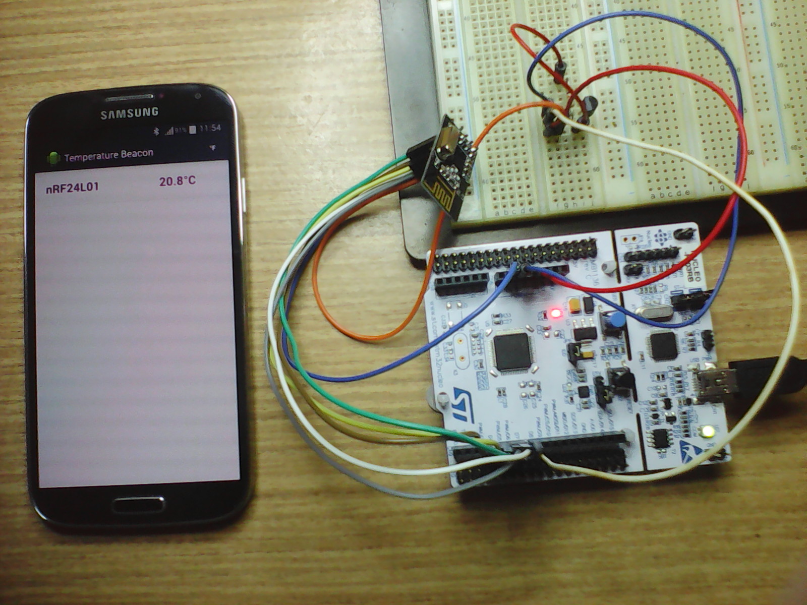
Bluetooth Low Energy (BLE) beacon with nRF24L01(+). Data is received and displayed by Android device (Android app source code is attached).
nRF24L01 as Bluetooth Low Energy (BLE) Broadcaster/Beacon
Temperature measured by a DS1820 sensor is broadcasted by a nRF24L01(+) module as Bluetooth Low Energy signal. Data is then received and displayed on an Android device (smartphone/tablet) with Bluetooth Low Energy (Bluetooth Smart) enabled. In order to have Bluetooth LE available your device should run Android 4.3 or more recent.
Needed parts:
- mbed module
- nRF24L01 or nRF24L01+ module
- DS18B20 or DS18S20 sensor
- 4.7k Ohm resistor
- Wires
- Breadboard
- Android device with Bluetooth LE enabled (Android 4.3 or more recent)
Zoom in

Figure 1: The hookup and the Android app in action
It was Dmitry Grinberg who figured out how to use nRF24L01 for BLE.
Read his amazing "Bit-banging" Bluetooth Low Energy.
Thank you Dmitry!
I ported the code to mbed from Lijun's repository.
Read his very neat article on the topic.
Thank you Lijun!
It takes just few steps to build a Temperature Beacon
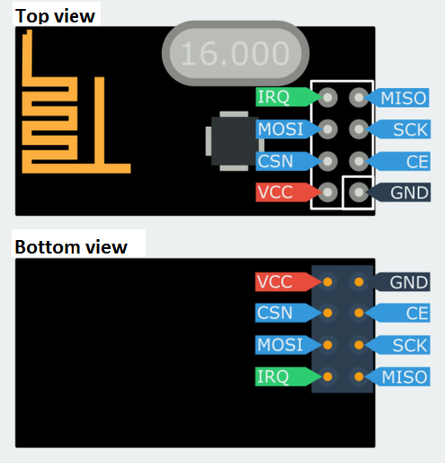
- Connect the nRF24L01(+) module and the DS1820 sensor to the mbed board according to the pin assignment defined in main.cpp. Don't forget to connect a 4.7k Ohm resistor between the DS1820's data pin and the +3.3V pin.

Figure 2: nRF24L01(+) pinout
- Compile the project and save the binary file to your mbed module.
- Enable Bluetooth on the Android device.
- To view the raw data, install Nordic's nRF Master Control Panel (available at Google Play for free) to your Android device. Run the app and wait until a new nRF24L01 device is found. Do not tap the CONNECT button. This device is a broadcaster and enables only one way data flow (from the mbed to the Android). To see more details, tap the found nRF24L01 device on the left side of the screen and then the small RAW button which appears on the right side just below the CONNECT button. Now you should be able to see and check the raw bytes received from the mbed.
- Install the Android app:
- Download the TemperatureBeacon app to your computer's folder of choice.
- Open the folder and copy (send via Bluetooth or USB cable) the downloaded file to your Android device.
- To install the app, open the folder on the Android with the file downloaded in the previous step and tap it. - Once the app is installed and running:
- After a while you should see the temperature displayed on Android (See in Figure 1).
- Data is periodically updated. To verify that, touch the DS1820 sensor and you should see some new values.
If you'd like to adapt the Android app to your taste
- Install Android Studio onto your computer (Window, Mac, Linux). It's a fantastic IDE from Google for free.
- Download the Android app project to your computer's folder of choice and unzip.
- Start Android Studio, open the project downloaded in the previous step and have fun.
I have learnt a lot about Android and Bluetooth Low Energy here:
https://developer.android.com/guide/topics/connectivity/bluetooth-le.html,
https://thenewcircle.com/s/post/1553/bluetooth_smart_le_android_tutorial
The Android app is based on:
https://github.com/devunwired/accessory-samples/tree/master/BluetoothGatt.
Thank you Dave!
Diff: main.cpp
- Revision:
- 6:14d70104b0fc
- Parent:
- 5:448e87318747
- Child:
- 7:79c3ff270db1
diff -r 448e87318747 -r 14d70104b0fc main.cpp
--- a/main.cpp	Sun Jun 07 09:32:39 2015 +0000
+++ b/main.cpp	Tue Dec 15 19:34:51 2015 +0000
@@ -2,9 +2,11 @@
 Using nRF24L01(+) as a Bluetooth Low Energy Advertiser/Broadcaster/Beacon
 by hacking an nRF24L01(+) module (which is under $1 per unit on eBay).

+See wiki page: <https://developer.mbed.org/users/hudakz/code/BLE_nRF24L01>
+
 Note: It works with both nRF24L01 and nRF24L01+ modules.

-In this project we broadcast temperature readings measured by a DS1820 chip.
+Temperature readings measured by a DS1820 chip are broacasted over Bluetooth LE.
 (You can easily modify the code to broadcast some other custom data.
  Only make sure not to exceed the 32 bytes packet length.)

@@ -25,7 +27,7 @@
 #endif

 // The MAC address of BLE advertizer -- just make one up
-// If you decide to ceate more Beacons make sure that MAC address (MY_MAC) is unique (differs)
+// If you decide to ceate more Beacons make sure that MAC address (MY_MAC) is unique for each beacon

 #define MY_MAC_0    0x11
 #define MY_MAC_1    0x12
@@ -39,46 +41,18 @@
 DigitalOut  cs(p8);                 // CSN  (select SPI chip/slave)
 DigitalOut  ce(p14);                // CE   (enable nRF24L01 chip)
 DS1820      ds1820(p15);            // create a ds1820 sensor
-#elif defined(TARGET_FRDM_KL25Z)
-SPI         spi(PTD2, PTD3, PTD1);  // MOSI, MISO, SCK
-DigitalOut  cs(PTD0);               // CSN  (select SPI chip/slave)
-DigitalOut  ce(PTD5);               // CE   (enable nRF24L01 chip)
-DS1820      ds1820(PTA13);          // create a ds1820 sensor
-#elif defined(TARGET_FRDM_KL46Z)
-SPI         spi(PTD2, PTD3, PTD1);  // MOSI, MISO, SCK
-DigitalOut  cs(PTD0);               // CSN  (select SPI chip/slave)
-DigitalOut  ce(PTD5);               // CE   (enable nRF24L01 chip)
-DS1820      ds1820(PTA13);          // create a ds1820 sensor
-#elif defined(TARGET_LPC11U24)
-SPI         spi(P16, P15, P13);     // MOSI, MISO, SCK
-DigitalOut  cs(P17);                // CSN  (select SPI chip/slave)
-DigitalOut  ce(P18);                // CE   (enable nRF24L01 chip)
-DS1820      ds1820(P10);            // create a ds1820 sensor
-#elif defined(TARGET_NUCLEO_F030R8)
-SPI         spi(PB_5, PB_4, PB_3);  // MOSI, MISO, SCK
-DigitalOut  cs(PB_10);              // CSN  (select SPI chip/slave)
-DigitalOut  ce(PA_8);               // CE   (enable nRF24L01+ chip)
-DS1820      ds1820(PA_9);           // creates a ds1820 sensor
-#elif defined(TARGET_NUCLEO_F072RB)
-SPI         spi(PB_5, PB_4, PB_3);  // MOSI, MISO, SCK
-DigitalOut  cs(PB_10);              // CSN  (select SPI chip/slave)
-DigitalOut  ce(PA_8);               // CE   (enable nRF24L01 chip)
-DS1820      ds1820(PA_9);           // creates a ds1820 sensor
-#elif defined(TARGET_NUCLEO_F103RB)
-SPI         spi(PB_5, PB_4, PB_3);  // MOSI, MISO, SCK
-DigitalOut  cs(PB_10);              // CSN  (select SPI chip/slave)
-DigitalOut  ce(PA_8);               // CE   (enable nRF24L01 chip)
-DS1820      ds1820(PA_9);           // create a ds1820 sensor
-#elif defined(TARGET_NUCLEO_F401RE)
-SPI         spi(PB_5, PB_4, PB_3);  // MOSI, MISO, SCK
-DigitalOut  cs(PB_10);              // CSN  (select SPI chip/slave)
-DigitalOut  ce(PA_8);               // CE   (enable nRF24L01 chip)
-DS1820      ds1820(PA_9);           // creates a ds1820 sensor
-#elif defined(TARGET_NUCLEO_F411RE)
-SPI         spi(PB_5, PB_4, PB_3);  // MOSI, MISO, SCK
-DigitalOut  cs(PB_10);              // CSN  (select SPI chip/slave)
-DigitalOut  ce(PA_8);               // CE   (enable nRF24L01 chip)
-DS1820      ds1820(PA_9);           // creates a ds1820 sensor
+#elif defined(TARGET_NUCLEO_F103RB) || defined(TARGET_NUCLEO_L152RE) || defined(TARGET_NUCLEO_F030R8)  \
+   || defined(TARGET_NUCLEO_F401RE) || defined(TARGET_NUCLEO_F302R8) || defined(TARGET_NUCLEO_L053R8)  \
+   || defined(TARGET_NUCLEO_F411RE) || defined(TARGET_NUCLEO_F334R8) || defined(TARGET_NUCLEO_F072RB)  \
+   || defined(TARGET_NUCLEO_F091RC) || defined(TARGET_NUCLEO_F303RE) || defined(TARGET_NUCLEO_F070RB)  \
+   || defined(TARGET_KL25Z ) || defined(TARGET_KL46Z) || defined(TARGET_K64F) || defined(TARGET_KL05Z) \
+   || defined(TARGET_K20D50M) || defined(TARGET_K22F) \
+   || defined(TARGET_NRF51822) \
+   || defined(TARGET_RZ_A1H)
+SPI         spi(D11, D12, D13);     // MOSI, MISO, SCK
+DigitalOut  cs(D6);                 // CSN  (select SPI chip/slave)
+DigitalOut  ce(D7);                 // CE   (enable nRF24L01 chip)
+DS1820      ds1820(D8);             // create a ds1820 sensor

 // If your board/plaform is not present yet then uncomment
 // the following five lines and replace TARGET_YOUR_BOARD, SPI_MOSI, SPI_MISO, SPI_SCK, SPIS_CS, CE_PIN and DS1820_DATA_PIN as appropriate.
@@ -260,6 +234,7 @@
     uint8_t  ch = 0;
     uint8_t  data[4];
     float*   temp = reinterpret_cast <float*>(&data[0]);
+    int      error = 0;

     // Chip must be deselected
     cs = 1;
@@ -302,14 +277,23 @@
         return 1;
     }

-    ds1820.startConversion();   // Start temperature conversion
-    wait(1.0);                  // let DS1820 complete the temperature conversion

     while(1) {
-        *temp = ds1820.read();
+        ds1820.startConversion();   // Start temperature conversion
+        wait(1.0);                  // let DS1820 complete the temperature conversion
+        error = ds1820.read(*temp); // read temperature from DS1820 and perform cyclic redundancy check (CRC)

 #if DEBUG
-        serial.printf("temp = %3.1f'C\r\n", *temp);
+        switch(error) {
+        case 0:    // no errors -> '*temp' contains the value of measured temperature
+            serial.printf("temp = %3.1f\r\n", *temp);
+            break;
+        case 1:    // no sensor present -> '*temp' is not updated
+            serial.printf("no sensor present\n\r");
+            break;
+        case 2:    // CRC error -> '*temp' is not updated
+            serial.printf("CRC error\r\n");
+        }
 #endif

         buf[i++] = 0x42;            // PDU type, given address is random; 0x42 for Android and 0x40 for iPhone
@@ -370,7 +354,5 @@
         ce = 1;                     // Enable Chip
         wait_ms(50);
         ce = 0;                     // (in preparation of switching to RX quickly)
-        ds1820.startConversion();   // Start temperature conversion
-        wait(1.0);                  // Broadcasting interval (shall be > DS1820 temperture converion time)
     }
 }