QEI_hw interface implementation notes
The QEI_hw library that is found on my Libraries page requires hardware modification of the mbed module. The usual disclaimer applies : modifying the mbed will void the warranty and, if you make a mistake, you could end up with permanent damage. So proceed with caution!
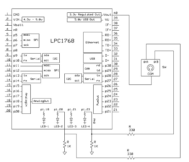
The rotary encoder must be connected to nodes p1.20 and p1.23. These nodes are also used to connect LED2 and LED4, respectively, on the mbed module.
The necessary hookup for a simple mechanical panel encoder is shown in the following schematic diagram:
 |
| From mbed |
In deciding how to hook up the encoder, I took care to minimize the chance of overloading the mbed should the user inadvertently use LED2 or LED4 when the encoder is connected. So the encoder does not directly switch p1.20 or p1.23 to either ground or Vout. Had that been done, the port would see a short circuit when trying to turn the port pins on or off, respectively.
The encoder pulls the port pins up through 330 ohm series resistors to +3.3 volts. When the encoder breaks contact, the port pins are pulled down passively by 1K ohm resistors to ground. This scheme works well for panel encoders turned by humans. For very high-speed encoders, as might be found on motor shafts, the passive pull down may be too slow; in that case an active interface would be preferred.
While not for the novice, the mods are feasible for anyone who has access to a few modern tools.
Tools required:
- A low-wattage, temperature controlled soldering iron with a fine tip (suitable for working with surface-mount devices). A Weller WES51 is one example.
- Very fine insulated wire. 30 AWG (0.05 mm2 ) wire-wrap wire should work.
- Needle nose pliers, diagonal cutters, wire-stripper, solder, magnifying glass, etc.
Modification steps:
- Place the mbed module top down on the work surface. An anti-static mat is suggested.
- Locate the two gold-plated holes shown in the following photo:
| From mbed |
- Solder one wire to each hole.
- Connect the 1K ohm pull-down resistors, and the 330 ohm series resistors to the end of each wire, as shown in the schematic.
- Connect the other end of each series resistor to one of the encoder phase terminals. It really doesn't matter which one, as you can adjust the sense of rotation with the direction invert parameter of the initialization method.
- Connect the common terminal of the encoder to +3.3 volts.
Here is a picture after the wires have been soldered to the mbed:
| From mbed |
You are now good to go.
12 comments
You need to log in to post a comment


Great work!
This is just what I was looking for for use with high speed motor encoders - Thanks