Mbed-controlled Robotic Arm (1/2)

GT ECE 4180 Fall 2011 (Lab 3)
- gvalentin3
- ebernstein6
Note: This post was our original inspiration
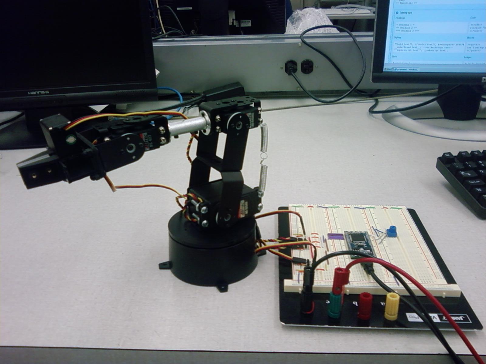
We use a slightly less expensive version than the one shown in the image.
Materials
- Hardware-only Lynxmotion AL5A
- 3 Hi-Tec HS-422 RC Servos (or HS-322)
- 1 Hi-Tech HS-755HB RC Servo (This servo is larger than the others)
- 1 Hi-Tech HS-645MG RC Servo
- Power supply
- Object to be used as arm base
- Mechanism to hold robot base to object base (Gorilla tape will do the trick)
Assembly
Information
Ignore any reference(s) to the Lynmotionx controller since we will be using the hardware only kit controlled by the mbed.
Discrepancy with Picture
The diagram corresponding to the mounting of the last (mini) C bracket seems to be different from the picture. (We believe the picture is correct)
Thanks to Dr. Allen Robinson for helping us figure this (and other things) out!


Verify your Springs!
Some Lynxmotion kits contain the wrong load balancing springs. The ones required are 1.5" 1.58lb NOT 2.5" 3.61lb.
If no springs are used, the servos will be unable to fully sustain the weight of the arm and the current draw will increase substantially.
Conventions
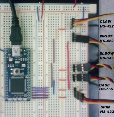
In the robo class, the servos are named in the following way (starting from bottom to top)
- claw = p25
- wrist= p24
- elbow= p23
- base = p22
- spin = p21
Connections

The Robo Class
Import programRoboArm
Robo class for controlling Lynxmotion AL5A Arm
Movements and Limitations
| Claw | Wrist | Elbow | Base | Spin |
|---|---|---|---|---|
| Full Open = 1.5ms | Straight=1ms | Forward=1ms | Flat=1ms | Full ccw=1ms |
| Closed = 2ms | Limit=1.6ms | Full Bac=2ms | Limit=1.7ms | Full cw=2ms |
Note1: Front and back directions are relative to the springs
Note2: Some limitations might vary for different configurations
Test
Please log in to post comments.
