Driving a controllerless QVGA display
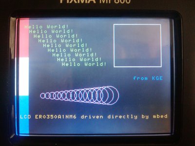
Here is the mbed driving a controllerless LCD ER0350A1NM6. The display is supposed to do 65k colors but since there is so little information available I could not find out how you can send more than 3 bit data to each pixel. The data for each line is pushed every 80 usecs by a ticker routine. By using PortOut it is possible to send 120 bytes per line and still have a reasonable amount of CPU power left to do some graphics primitives.

10 comments on Driving a controllerless QVGA display:
On the web I found a single sheet PDF in which the 20 pin connection is described.
The datasheet has some contradiciting texts: pin 6 is named 'VLCD'in the table but in the drawing it is named FLM.
No timing or dataformat is mentioned.
By combining some other info on the web from similar devices I finally deduced a way of driving the pins with the right signals. By using 3 bits per pixel I needed already 28k of framebuffer ram from the mbed.
I have been trying to get a 480*272 24bit W-QVGA to work,
this also has no controller chip,
I am only just able to draw a few different colored bars,
with a sharp image,
although I have managed to draw a bitmap, but the refresh rate is so low
that the image fades almost as soon as it is drawn/written :(
I have been looking for other micros, that have a display controller/memory interface,
but have not found a suitable one yet.
I have been told there is a LPC????? which has enough toys inside to do the job.
Regards
Ceri
Hi Ceri,
There's the LPC2478 which includes an on-board LCD controller - we've had that driving 800x600 in 16 bit colour with external SDRAM to hold the display image(s).
There will also be the LPC1788 available later this year which is effectively the LPC2478 but with the ARM7 TDMI core replaced with the Cortex M3
Both have a total of 96k (arranged as 64+16+16) of internal SRAM which may be enough for holding smaller display images.
HTH
Cheers,
Jez
By using the ABSHRAM0 and ABSHRAM1 spaces I managed to move the framebuffer into 'the other' 32k space, freeing the normal ram space again for mbed use. My testbed does not use the Ethernet, CAN or USB function so this space was unused. By using PortOut and the smallest interrupt routine I could come up with, every line is drawn within the 80 usecs time period of the ticker. The remaning time is for the main program. Picture refresh is 52 Hz now so it is nice and stable. Maybe by converting the interrupt routine to pure assembler it would take even less cycles. I would love to see the generated code for this routine:
// the main interrupt routine, runs every 80 usecs
inline void LineInterrupt() {
    unsigned int t;

    if (pointer==FRAMEBUFFERMAX) {    // when end of framebuffer
        pointer=0;          // reset pointer
        FLM=1;              // signal new frame
        FR=!FR;             // toggle FR
    } else {
        FLM=0;              // else reset FLM
    }

    // shift a line of the framebuffer out
    for (t=0; t<120; t++) {
        CL2=1;
        mybus=framebuffer[pointer++]<<4;
        CL2=0;
    }
    CL1=1;      // set line latch pulse
    CL1=0;      // reset line pulse
}
I can imagine that driving 480x272 in 24bit mode is undoable because of the large amount of ram needed. I still haven't found out how to use more than 3 bit/pixel on my 320x240 display, but then again if it really used 5 bits per color I would need 153k of ram...
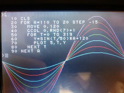
Mixing the Z80 emulator and BBC Basic with this display leads up to this:

Optimized to the max:
Shuffling some port pins around so all the fast pins are on port 0
// LCD pins (new pinout, all the fast pins on port 0)
DigitalOut  CL2(p9);        // p0.0  = data clock
DigitalOut  CL1(p10);       // p0.1  = line clock
DigitalOut  FR(p17);        // p0.25 = frame AC input (alternating 0/1)
DigitalOut  FLM(p18);       // p0.26 = first line marker
DigitalOut  LED_ON(p20);    // p1.31 = backlight enable bit
DigitalOut  nDISP(p23);     // p2.3  = databus enable
DigitalOut  VLCD_ON(p24);   // p2.2  = lcd electronics on/off
PwmOut      VLCD_PWM(p26);  // p2.0  = contrast PWM input

// define our 8+2 bit port
#define PORT0MASK 0x00000FF3      // p0.4-p0.11 is 8 bit data p0.0=CL2 p0.1=CL1
PortOut mybus(Port0, PORT0MASK);  // only used for port initialisation

// framebuffer space 240 lines of 120 bytes equals 28800 bytes
// force this framebuffer in ABSHRAM0 and ABSHRAM1
// warning!! this disables the use of the USB, Ethernet and CAN bus functions!

unsigned char *framebuffer = (unsigned char *)(0x2007C000);

// the pointer in the frambuffer
volatile unsigned int pointer=0;

#define FRAMEBUFFERMAX 28800

// direct access pointer to port0
volatile uint32_t *myport0= (volatile uint32_t *) 0x2009c000;

// high burden interrupt...
Ticker LineTimer;

// the main interrupt routine, runs every 80 usecs
inline void LineInterrupt() {
    unsigned char t;
    unsigned int s;

    *(myport0+7)=2;                     // clear line latch pulse CL1 = 0

    if (pointer==FRAMEBUFFERMAX) {      // when end of framebuffer
        pointer=0;                      // reset pointer
        *(myport0+6)=1<<26;             // signal new frame FLM = 1
        FR=!FR;                         // toggle FR
        systemclock++;                  // increment system clock
    } else {
        *(myport0+7)=1<<26;             // always reset FLM
    }

    // shift a line of the framebuffer out
    for (t=120; t>0; t--) {            // 120 bytes to go (counting down is faster)
        s=1|framebuffer[pointer++]<<4; // preshift data and set CL2 to 1
        *(myport0+7)=0x00000FF0;       // clear all 8 data bits of port0
        *(myport0+6)=s;                // set the 1 bits of s on port0
        __nop();                       // slow down
        __nop();                       // and stretch CL2
        *(myport0+7)=1;                // reset CL2 to 0;
    }
    *(myport0+6)=2;                    // set line latch pulse CL1 = 1
}                                      // interrupt done

// ================================================================
//  main program
// ================================================================
int  main() {

    // switch on LCD screen as early as possible
    LED_ON=1;                  // backlight on
    VLCD_PWM.period(0.00020);  // PWM period for contrast adjust
    VLCD_PWM=0.25f;            // set contrast
    VLCD_ON=1;                 // LCD electronics on
    nDISP=1;                   // enable data input on display
    CL1=0;                     // start with clock lines low
    CL2=0;                     // CL1 and CL2
    FLM=0;                     // first line marker

    // start the interrupt in 80 usec mode
    LineTimer.attach_us(&LineInterrupt,80);

    // display is active now, rest of your program here
    while (1){
    }

}
This resulted in an increase of more than 30% of remaining CPU power outside the interrupt.
Is it possible to show us/me some more of the code please,
Also, I do not understand what the ..+7.. bit of *(myport0+7)=s is doing ?
As for my design, using 480*272, I have 12 lines for RGB,
and I want to add some code (probably lots) to read images etc from SD Card.
and hopefully using the touch screen in some way.
Cheers
Ceri
Is it possible to show us/me some more of the code please,
I added some more relevant code
Also, I do not understand what the ..+7.. bit of *(myport0+7)=s is doing ?
As for my design, using 480*272, I have 12 lines for RGB,
and I want to add some code (probably lots) to read images etc from SD Card.
and hopefully using the touch screen in some way.
Cheers
Ceri
Hi Ceri,
the +6 and +7 are the offsets for the bit set and reset registers of port 0, I copied that from the fastlib library http://mbed.org/users/Ivop/libraries/fastlib/ltrmdj just simplified the call a bit to make it even faster.
If you compare the source above with the one at the beginning of this thread (with all the seperate pin set and reset instructions) you will find the similarities.
I moved the clear line latch pulse to the beginning of the interrupt (it does not matter for the display) otherwise the set and clear would be too close and the lcd would not register it. (that's how fast direct acces works!)
My framebuffer is a contiguous piece of ram where 3 bytes in a row hold single bit RGB data for a pixel: RGBRGBRG BRGBRGBR GBRGBRGB and then the pattern repeats. 120 Bytes are needed for a single line of 320 pixels. This framebuffer is located in the (in my project) unused 32k Ethernet/USB/CAN bus ramspace (ABSHRAM0 and ABSHRAM1) of the mbed.
Not to rain on your parade: You will totally run out of ramspace if you want to connect all 12 bits and use the full 480*272 resolution in a framebuffer: you have to push out 12 bits for each pixel! I only have to push out 3 for each pixel (limiting the number of colors to just 8)
Maybe it is possible to read an image line from the SD card and display it on the fly but it is unlikely you can do that in the limited time per scanline available... Controllerless LCDs need to be updated at least 50 times per second, with 272 lines you need to send (480*12bits)/8=720 bytes in less than 72 usecs..
Gert
crazycreator13
#
12 Mar 2013
I understand that you push out the 120 bytes for one line, but how do you get to the next line? Can you skip lines? In order to skip a like do you need to send dummy/empty bytes?
I understand that you push out the 120 bytes for one line, but how do you get to the next line? Can you skip lines? In order to skip a like do you need to send dummy/empty bytes?
the line:
*(myport0+6)=2; // set line latch pulse CL1 = 1
latches the data to the LCD panel and advances the internal linecounter of the display. The linecounter is reset by the FLM signal.
You could send (for my display) 120 bytes of dummy bytes but they will show up on the display when you trigger the line latch pulse CL1. If you send 120 null bytes the display will be black for that line.
Please log in to post comments.


On the web I found a single sheet PDF in which the 20 pin connection is described. The datasheet has some contradiciting texts: pin 6 is named 'VLCD'in the table but in the drawing it is named FLM. No timing or dataformat is mentioned. By combining some other info on the web from similar devices I finally deduced a way of driving the pins with the right signals. By using 3 bits per pixel I needed already 28k of framebuffer ram from the mbed.