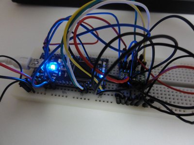
MMA7455L connected via SPI
This is just the first attempt to work with MMA7455L.
- MMA7455L sensor module http://strawberry-linux.com/catalog/items?code=12102
- Code is based on the following application note: http://strawberry-linux.com/pub/AN3468.pdf
- CS should be connected to any pin other than P19 which is off(0); I'm not sure but controlling CS does not work as expected.
- Pulse Detection does not work though P15 is flagged; what should I do next?
- 10bit is only enabled for 8g according to page 15 of the spec. above.
- It seems that we should accumulate values (for a delta time) from a sensor to get consistent result.
- LEDs is used to indicate the activities on those sensors.
- Add negative number support (for reading 10-bit value)
// Testing MMA7455L SPI
#include "mbed.h"

SPI spi(p5, p6, p7);
DigitalOut cs(p19);
InterruptIn int1(p15), int2(p16);
Serial pc(USBTX, USBRX);
DigitalOut led1(LED1), led2(LED2), led3(LED3);

int read(int reg) {
    cs = 0;
    int v = spi.write(reg << 1);
    cs = 1;
    return v;
}

void write(int reg, int val) {
    cs = 0;
    spi.write(0x80 | (reg << 1));
    spi.write(val);
    cs = 1;
}

int read10(int reg) {
    cs = 0;
    int v = spi.write(reg << 1);
    v |= spi.write((reg + 1) << 1) << 8;

    if(v & 0x200)
        v = v - 1024;

    cs = 1;
    return v;
}

int readSensorDirect(int sensor) {
    return read10(sensor * 2);
}

const int SENSBUFSIZE = 100;
int sensbuf[3][SENSBUFSIZE];
int sens_ptr = 0;

void reset()
{
    for(int i = 0; i < 3; i++)
    {
        int offset = readSensorDirect(i);
        write(0x10 + i * 2, offset * 2);
    }
    memset(sensbuf, 0, sizeof(sensbuf));
}

void accumulate()
{
    for(int i = 0; i < 3; i++)
        sensbuf[i][sens_ptr] = readSensorDirect(i);
    sens_ptr++;
    if(sens_ptr == SENSBUFSIZE)
        sens_ptr = 0;
}

int readSensor(int sensor)
{
    int* buf = sensbuf[sensor];
    int a = 0;
    for(int i = 0; i < SENSBUFSIZE; i++)
        a += buf[i];
    return a;
}

void int1_raised() {
    pc.printf("1\n");
    //pc.printf("1: %06d,%06d,%06d\n", readX(), readY(), readZ());
}

void int2_raised() {
    pc.printf("2\n");
    //pc.printf("2: %06d,%06d,%06d\n", readX(), readY(), readZ());
}

const int INDSIZE = 5;
const int FULLSIZE = INDSIZE * 2 + 1;

void bar(char* ind, int v)
{
    memcpy(ind, "..........|.........." + (10 - INDSIZE), FULLSIZE);
    if(v < 0)
    {
        char* p = ind + INDSIZE - 1;
        for(int i = 0; i < INDSIZE; i++)
        {
            if(v) *p = '#';
            p--;
            v /= 5;
        }
    }
    else
    {
        char* p = ind + INDSIZE + 1;
        for(int i = 0; i < INDSIZE; i++)
        {
            if(v) *p = '#';
            p++;
            v /= 8;
        }
    }
}

int main() {

    wait_ms(300);

    spi.format(8, 0);
    spi.frequency(1 * 1000* 1000);

    // Device ID
    read(0xf);
    pc.printf("WHOAMI: %02X\n", read(0xf));

    // $16: Mode Control Register
    // 0x0: Standby Mode
    // 0x1: Measurement Mode
    // 0x2: Level Detection Mode
    // 0x3: Pulse Detection
    int mode = 0x2;

    // 0x0: 8g
    // 0x8: 4g
    // 0x4: 2g
    int glv = 0x0;

    read(0x16);
    write(0x16, glv | mode);
    pc.printf("Mode Control Register: %02X\n", read(0x16));

    // Optimal Settings for Freefall using Level Detection
    // 1. THOPT=0 Absolute Condition
    // 2. ZDA=0 Enable Z, YDA=0 Enable Y, XDA=0 Enable X
    write(0x18, read(0x18) & 0x87);
    // 3. Negative AND Logia Set LDPL
    write(0x19, read(0x19) & 0x1);
    // 4. Set Threshold = 1 g
    write(0x1a, 0x10);

    /*
    // Optimal Settings for Motion using Level Detection
    // 1. THOPT=0 Absolute Condition
    // 2. ZDA=1 Disable Z, YDA=0 Enable Y, XDA=0 Enable X
    write(0x18, (read(0x18) & 0x87) | 0x20);
    // 3. Positive OR Logic Clear LDPL
    write(0x19, read(0x19) & 0xfe);
    // Set Threshold to 2 g
    write(0x1a, 0x20);
    */

    /*
    // Optimal Settings for Single Pulse Detection
    // 1. Positive OR Logic PDPL=0
    write(0x19, read(0x19) & 0xfd);
    // 2. X,Y,Z enabled
    write(0x18, read(0x18) & 0x87);
    // 3. PDTH (Pulse Threshold) set to 4 g
    write(0x1b, 0x40);
    // 4. PD (Pulse Duration) set to 8 ms
    write(0x1c, 0x80);
    */

    int1.rise(int1_raised);
    int2.rise(int2_raised);

    reset();
    for(int i = 0;; i++)
    {
        wait_us(100);
        accumulate();

        int x = readSensor(0);
        int y = readSensor(1);
        int z = readSensor(2);
        led1 = x / 100;
        led2 = y / 100;
        led3 = z / 100;

        if (i % 100 == 0)
        {
            char buf[FULLSIZE * 3 + 3];
            memset(buf, ' ', FULLSIZE * 3 + 2);
            buf[FULLSIZE * 3 + 2] = 0;
            bar(buf, x);
            bar(buf + FULLSIZE + 1, y);
            bar(buf + (FULLSIZE + 1) * 2, z);

            pc.printf("P:%s\n", buf);
        }
    }
}
1 comment
You need to log in to post a comment
MMA7455L connected via SPI
The first attempt to use MMA7455L on SPI.
Page owner:  Takashi Kawasaki
Created 22 Jul 2010.
Last updated 23 Jul 2010
Thanks for the code,
could you post a wiring diagram as I'm unsure which pins MISO and MOSI are connected to on the MMA7455.
Thanks again,
Sam