Etch-A-Sketch
Overview
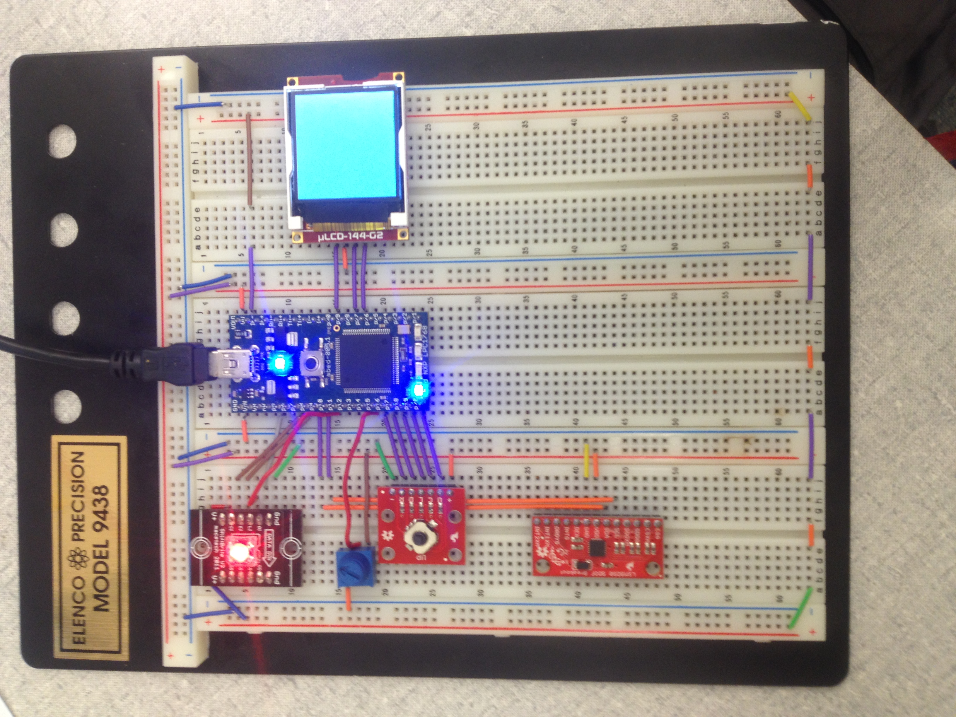
This is an mbed version of a classic toy. The Etch-A-Sketch screen is a uLCD, with location input from the up, down, left, and right outputs of a 5-way switch. Two potentiometers could also be used to make the input a bit more authentic, but we found that the limited range of motion relative to the screen size with these made 'sketching' on the LCD a bit difficult. An LMS9DS0 IMU is used to detect shaking, which triggers the LCD screen to clear. We also added color selection to make drawing cool pictures easier. A potentiometer is used to scroll through RGB values, with the resulting color displayed by a Shiftbrite. The center button on the 5-way switch toggles between red, green, and blue. The LEDs on the actual mbed indicate which is currently selected, though it is pretty easy to tell by simply rotating the potentiometer and seeing how the color is affected.
The program runs three threads: one for color selection, one for erasure detection, and the other for drawing input/output.
Wiring Tables
IMU
The IMU uses an I2C bus, and takes 3.3V power.
| mbed | LMS9DS0 IMU |
|---|---|
| VOUT | VDD |
| GND | GND |
| p9 | SDA |
| p10 | SDL |
Shiftbrite
The Shiftbrite uses an SPI bus, and takes 5V power. It also requires two DigitalOut pins for control logic (see the wiki page for more information on their function).
| mbed | Shiftbrite |
|---|---|
| VU(5.0v) | V+ |
| GND | Gnd |
| p5 | DI |
| p7 | CI |
| p8 | EI |
| p11 | LI |
uLCD
The uLCD uses a serial interface, along with a reset control pin. See the wiki page for more information. Since the entire breadboard is shaken to erase the current image, you definitely want to have the uLCD plugged directly into the breadboard, as opposed to hooked up via a cable.
| mbed | uLCD cable |
|---|---|
| VU(5.0v) | 5V |
| GND | GND |
| p28 | TX |
| p29 | RX |
| p30 | Reset |
Potentiometer
The potentiometer can be hooked up to any AnalogIn pin. It takes 3.3V power.
5-Way Switch
Each output of the 5-way switch can be hooked up to any DigitalIn pin. These are active low inputs. The switch takes 3.3V power.

Code
#include "mbed.h"
#include "LSM9DS0.h"
#include "rtos.h"
#include "uLCD_4DGL.h"

// SDO_XM and SDO_G are pulled up, so our addresses are:
#define LSM9DS0_XM_ADDR  0x1D // Would be 0x1E if SDO_XM is LOW
#define LSM9DS0_G_ADDR   0x6B // Would be 0x6A if SDO_G is LOW

//Accelerometer over I2C
LSM9DS0 imu(p9, p10, LSM9DS0_G_ADDR, LSM9DS0_XM_ADDR);

//Shiftbrite over SPI and control pins
SPI shiftbrite(p5, p6, p7);
Mutex color_lock;
DigitalOut latch(p11);
DigitalOut enable(p8);

//Potentiometer
AnalogIn dial(p15);

//LCD over serial, and mutex for cross-thread accesses
uLCD_4DGL lcd(p28, p27, p30);
Mutex lcd_lock;

//5-way switch (ActiveLow)
DigitalIn right(p16);
DigitalIn down(p17);
DigitalIn left(p18);
DigitalIn center(p19);
DigitalIn up(p20);

//Color selection output vars
int selector = 0;
DigitalOut red_sel(LED1);
DigitalOut green_sel(LED2);
DigitalOut blue_sel(LED3);

//current location on lcd   NOTE: the 'pixel' drawn is actually 4 pixels (on a 64x64 grid)
int pixel_x = 63;
int pixel_y = 63;
//Color value, locked via mutex for cross-thread access
int color_value = 0x8A2BE2;

//Thread checking for shaking (and clearing LCD if occuring)
void erase_thread(void const*args)
{
    while(true) {
        imu.readAccel();
        printf("%.2f %.2f %.2f\n", imu.ax, imu.ay, imu.az);
        if (imu.ax > .20 || imu.ay > .20 || imu.az > 1.5) { //threshold values for accelerometer 'shaking', raise to lower sensitivity
            lcd_lock.lock();
            lcd.cls();
            lcd_lock.unlock();
        }
        Thread::wait(500);
    }
}

//Thread updating/changing the color
void color_thread(void const*args)
{
    red_sel=1;
    int red=0;
    int green=0;
    int blue=0;
    unsigned int high=0;
    unsigned int low=0;
    while(true) {
        //Figure out which color selector is being used
        if (!center) {
            selector = (selector==2)? 0: selector + 1;
            //Display selector
            red_sel = (selector==0);
            green_sel = (selector==1);
            blue_sel = (selector==2);
        }
        //set the presently selected color value
        if (selector == 0)
            red = dial*0xFF;
        else if (selector == 1)
            green = dial*0xFF;
        else if (selector == 2)
            blue = dial*0xFF;
        //put color values into shiftbrite format
        high = (blue<<4) | ((red&0x3C0)>>6);
        low = (((red&0x3F)<<10)|(green));
        //write to the shiftbrite and latch values
        shiftbrite.write(high);
        shiftbrite.write(low);
        latch=1;
        latch=0;
        //update the color value (for use on the LCD)
        color_lock.lock();
        color_value = (red<<16)| (green<<8) | blue;
        color_lock.unlock();
        Thread::wait(500);
    }

}

//Main thread reads in tactile switch, draws to LCD
int main()
{
    //Initializations and set-up
    imu.begin();
    shiftbrite.format(16,0);
    shiftbrite.frequency(500000);
    enable=0;
    latch=0;
    wait(2);
    //launch threads
    Thread eraser(erase_thread);
    Thread color(color_thread);
    //change in pixel location indicator - reduces time LCD is locked unecessarily
    bool no_movement = false;
    //setup LCD screen
    lcd_lock.lock();
    lcd.background_color(0x606060);
    lcd.cls();
    lcd_lock.unlock();
    while(1) {
        no_movement = false; //flag indicating the joystick has been triggered
        if (!down && pixel_y != 0)
            pixel_y--;
        else if (!up && pixel_y!=63)
            pixel_y++;
        else if (!right && pixel_x!=0)
            pixel_x--;
        else if (!left && pixel_x!=63)
            pixel_x++;
        else
            no_movement = true;
        if (!no_movement) { // update the lcd screen
            lcd_lock.lock();
            color_lock.lock();
            lcd.filled_rectangle(pixel_x<<1, pixel_y<<1, (pixel_x<<1)+1, (pixel_y<<1)+1, color_value);
            color_lock.unlock();
            lcd_lock.unlock();
        }
        Thread::wait(100);
    }
}
Demo
Import programEtch-A-Sketch
Digital version of the classic game, with color selection.
Future Work
Future work on the Etch-A-Sketch might include substituting a potentiometer-based joystick, and having separate dials for the R, G, and B values.
Please log in to post comments.
