LPC812 MAX Experiment: I2C
Experiment: Work with a Serial Bus - I2C
In this experiment you will learn how to work with the Inter-Integrated Circuit Bus, or I2C bus for short. It is a multi-master bus for (relatively) low-speed peripherals. The basic clock frequency is 100 kHz but there are newer specifications that support higher speeds, for example 400 kHz that is often supported, called Fast-mode (Fm). Higher frequencies of 1 MHz (Fm+), 3.4 MHz (High-speed mode, Hs) and 5 MHz (Ultra Fast-mode, UFm) also exist but are less widespread.
The I2C bus is a synchronous bus meaning that there is an explicit clock signal. It builds on the masterslave concept where one unit is a master and controls the communication. One slave is addressed on the bus and is the other end of the master-slave communication. There can be many masters on the bus, but only one active at a time.
The I2C bus uses two bidirectional open-drain lines pulled up by resistors:
- SCK: serial clock, the master always generates the clock
- SDA: serial data, the master generates the data when transmitting to the slave. The slave generates the data when transmitting to the master
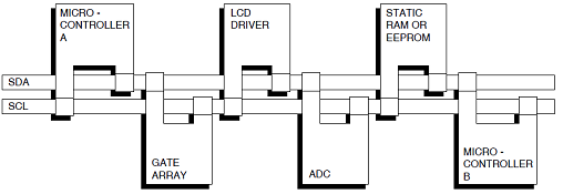
The picture below illustrates how many masters and slaves can share one I2C bus.

For more information about I2C, see http://en.wikipedia.org/wiki/I%C2%B2C. There is a lot of details about the I2C bus that have not been covered in this short overview, like how addressing works, how bus arbitration works, how read and write operations work, how acknowledge of data works, etc.
Have a look in chapter 16 - LPC800 I2C-bus interface in the LPC800 user’s manual for a description of the how the I2C block works. It is more complicated interface than for the timers and SSP peripherals. The basic principle is to send commands to the I2C peripheral block. These commands are carried out in the (external) I2C bus and a status is presented as result. Based on the status the I2C driver gives the next command.
The mbed library have an I2C class to make it easy to use the bus:
Import library
Public Member Functions |
|
| I2C (PinName sda, PinName scl) | |
|
Create an
I2C
Master interface, connected to the specified pins.
|
|
| void | frequency (int hz) |
|
Set the frequency of the
I2C
interface.
|
|
| int | read (int address, char *data, int length, bool repeated=false) |
|
Read from an
I2C
slave.
|
|
| int | read (int ack) |
|
Read a single byte from the
I2C
bus.
|
|
| int | write (int address, const char *data, int length, bool repeated=false) |
|
Write to an
I2C
slave.
|
|
| int | write (int data) |
|
Write single byte out on the
I2C
bus.
|
|
| void | start (void) |
|
Creates a start condition on the
I2C
bus.
|
|
| void | stop (void) |
|
Creates a stop condition on the
I2C
bus.
|
|
Not Implemented
At the time this guide was written the LPC800 I2C support was not fully functional. The block reading/writing functions:
read (int address, char *data, int length, bool repeated=false)
and
write (int address, const char *data, int length, bool repeated=false)
should not be used! Although it is annoying it is possible to work around it by using the byte functions instead. The examples in this lab uses the byte functions.
1) Hardware
In this lab you will need:
- 1x breadboard
- 4x 330 ohm resistor
- 1x yellow LED
- 1x green LED
- 2x trimming potentiometer
- cables
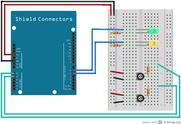
Mount the components on the breadboard and connect the breadboard to the LPC812 as show in the image below.

The pin(s) are specified in the mbed library with the actual pin names as well as some useful aliases:
| Schematic Name | mbed Pin Name | Arduino Shield Alias | Description |
|---|---|---|---|
| PIO0_10 | P0_10 | A4 | I2C SDC |
| PIO0_11 | P0_11 | A5 | I2C SCL |
| IOEXPAN4 | N/A | D5 | Yellow LED on I/O Expander |
| IOEXPAN5 | N/A | D6 | Green LED on I/O Expander |
| AIN0_XPIO0 (SJ5 in 1-2 pos) | N/A | A0 | Trimming capacitor 1 |
| AIN0_XPIO1 (SJ6 in 1-2 pos) | N/A | A1 | Trimming capacitor 2 |
1) Description
In this experiment a GPIO expansion chip, PCA9672, will be used. The chip features according to the user manual:
- 1 MHz I2C-bus interface (Fast-mode Plus I2C-bus)
- 8-bit remote I/O pins that default to inputs at power-up
- Active LOW reset input
- Active LOW open-drain interrupt output
The LPC812 MAX board has the PC9672 already mounted and the user push-button is connected to pin P7 of the expander.
According to the schematics the PCA9672 has address 0b0100011.
We have prepared a PCA9672 class to make it easier to use the gpio expander:
PCA9672.h
#ifndef PCA9672_H
#define PCA9672_H

#include "mbed.h"

//  PCA9672 IIC slave address
#define  PCA9672_ADDR 0x46


//!Library for the PCA9672 I/O expander.
/*!
The PCA9672 is an I2C I/O expander. It has 8 I/O pins.
*/
class PCA9672
{
public:
  /*!
  Connect PCA9672 to I2C port pins sda and scl.
  */
  PCA9672(PinName sda, PinName scl);

  /*!
  Set the frequency of the I2C interface.
  */
  void frequency(int hz);

  /*!
  Setup pin direction (bit = 1 for inputs, 0 for outputs)
  */
  void direction(uint8_t inputs);

  /*!
  Write the value to the IO Expander (pins XP0-XP7 output)
  */
  void write(char value);

  /*!
  Read the value of the IO Expander (pins XP0-XP7 input)
  */
  int read(void);

  /*!
  Destroys instance.
  */
  ~PCA9672();

private:

  I2C _i2c;
  uint8_t _pins;

};

#endif
PCA9672.cpp
#include "PCA9672.h"

PCA9672::PCA9672(PinName sda, PinName scl) : _i2c(sda, scl)
{
    // Software Reset
    _i2c.start();
    while(_i2c.write(0x00) !=1);
    while(_i2c.write(0x06) !=1);
    _i2c.stop();

    /* Software reset is not required. But, gives an
       indication if the selected I2C bus frequency works */
}

void PCA9672::frequency(int hz)
{
    _i2c.frequency(hz);
}

void PCA9672::direction(uint8_t inputs)
{
    _pins = inputs & 0xff;
}

void PCA9672::write(char value)
{
    if (_pins > 0)
    {
        _i2c.start();
        _i2c.write(PCA9672_ADDR);
        _i2c.write(value | _pins); // all input pins must have a logic 1 as value
        _i2c.stop();
    }
}

int PCA9672::read(void)
{
    _i2c.start();
    _i2c.write(PCA9672_ADDR | 1);
    uint8_t val = _i2c.read(0); // expect NACK
    _i2c.stop();
    return val;
}

PCA9672::~PCA9672()
{

}
main.cpp
#include "mbed.h"
#include "PCA9672.h"

PCA9672 ioxp(P0_10, P0_11); //I2C connected to PCA9672 in LPC800-MAX

Serial pc(USBTX, USBRX); // tx, rx

int main()
{
    ioxp.frequency(100000);
    ioxp.direction(0x80); // mark the push-button pin as input and the rest as outputs

    while (1) {
        uint8_t val = ioxp.read();
        pc.printf("Reading 0x%02x - bit 7 is %d\n", val, val>>7);
        if (val & 0x80)
        {
            ioxp.write(0x10);
        }
        else
        {
            ioxp.write(0x20);
        }
        wait(.50);
    }
}
Look at the code above and compare with the user manual and try to understand what the commands do.
Try to modify the program by replacing one of the LEDs on the breadboard with a push-button and then control the remaining LED to be on only when either push-button is pressed but not when both are pressed.
2) Hardware
The same setup is used so no changes are needed.
2) Description
There is no ADC (Analog to Digital Converter) or DAC (Digital to Analog Converter) on the LPC812 microcontroller, however the LPC812 MAX board has a PCF8591 chip which have four analog inputs and one analog output and is accessed with I2C.
You were given a PCF8591 helper class in the Analog Input experiment and now it is time to take a closer look at it.
Import librarylpc812_exp_lib_PCF8591
Library with PCF8591 support for the experiments for LPC812 MAX
PCF8591.cpp
#include "mbed.h"
#include "PCF8591.h"

PCF8591::PCF8591(PinName sda, PinName scl, int i2cAddr) : m_i2c(sda, scl)
{
    m_i2c.frequency(100000);
    m_addr = i2cAddr;
}

int PCF8591::read(AnalogIn port)
{
    char cmd = (port & 0x3); // read from selected port
    char data[2];

    // select the port
    m_i2c.start();
    m_i2c.write(m_addr);
    m_i2c.write(cmd);
    m_i2c.stop();

    // get the sample
    m_i2c.start();
    m_i2c.write(m_addr | 1);
    data[0] = m_i2c.read(1); // expect ACK
    data[1] = m_i2c.read(0); // expect NACK
    m_i2c.stop();

    // data[0] is a dummy byte so ignore it
    // data[1] is the new value
    return data[1];
}
The read function above starts by sending the Control byte as explained in section 8.2 of the user manual to prepare the chip to send data for the selected A/D channel.
After configuring the chip a sample is read. The A/D conversion is explained in section 8.3 and even if we only want one sample, two samples must be read. According to the user manual:
The first byte transmitted in a read cycle contains the conversion result code of the previous read cycle.
However the value seems to be random so we discard it and keep the second one instead.
Solution(s)
Import programlpc812_exp_solution_i2c
Solutions for the I2C experiments for LPC812 MAX
Please log in to post comments.
