LPC4088 QuickStart Board - Hardware Information
LPC4088 QuickStart Board Hardware Features
MCU
- LPC4088, Cortex-M4F core running at up to 120MHz
Memory
- 512 KByte on-chip FLASH
- 96 KByte on-chip SRAM
- 4 KByte on-chip E2PROM
- 8 MByte QSPI FLASH (can execute program code and/or contain a file system)
- 32 MByte SDRAM with 32-bit databus access
- On-board globally unique MAC address.
Connectors
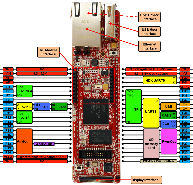
- 2x22 pin edge pins that are very compatible with the original 2x20 pin LPC1768 mbed pinning
- 10/100Mbps Ethernet (RJ45)
- USB-A (USB Host interface)
- USB-micro B (USB Device interface)
- USB-micro B (mbed HDK debug interface)
- 20 pos SWD/Trace connector (ARM standard debug connector)
- 61 pos 0.3mm pitch FPC connector for display expansion
- 20 pos XBee compatible connector for RF module add-on
Display expansion
- Up to 24-bit pixel data (16-bit most common) via 61 pos, 0.3mm pitch FPC connector.
Other
- Proper ESD protection on communication interfaces.
- On-board HDK (debug interface functions)
- Supported by the on-line mbed SDK.
- Supported by a lot of professional quality software and examples by EA.
- Industrial temperature specified (-40 to +85 degrees Celsius).
- ISO 9001 produced.
- Production compensated for carbon dioxide emission.
- Current consumption down to about 5 mA.
Pin Usage

- Schematic of board connectors
- Full schematic is available for product owners from Embedded Artists Support Site
- Excel sheet with LPC4088 pin usage
Pins not listed are used internally on the board or not used at all. In either case they are not available for expansion.
Key Components and Jumpers

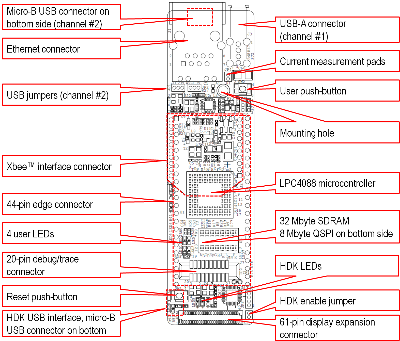
With the two USB jumpers it is possible to select if USB channel #2 (of the LPC4088) shall be connected to the on-board micro-B USB connector (under the RJ45 Ethernet connector) or to pin 35/36 on the edge connectors (which is compatible with the LPC1768 mbed module). The jumpers are located close to the RJ45 Ethernet connector:
- Left position: Connected to on-board micro-B USB connector
- Right position: Connected to pin 35/36 on the edge connector
The HDK enable jumper is located close to pin 23 and close to the FPC connector for display expansion. The jumper controls the HDK functionality:
- Jumper closed: The HDK functionality is enabled and active. Note that the HDK functionality will draw current all the time so low-power applications will not reach to the lowest possible current consumption values.
- Jumper open: The HDK functionality is disabled. The HDK functionality will not consume any current so this mode can be used when testing and measuring on low-power applications. Use this mode when connecting an external debug interface to the Cortex trace connector on the board. Also use this mode when the LPC4088 QuickStart Board is embedded into a product (and field-upgrade of the product is not needed).
Mechanical Information
- EAGLE library containing the LPC4088 QuickStart Board as a components.
- EAGLE project demonstrating display expansion to a base board. To be uploaded
- Information about mounting hole (suitable screw, suitable stand-off). To be added
- The FPC connector for display expansion is Hirose FH26-61S-0.3SHW(05). It is a 61 pos, 0.3mm pitch connector. Digikey stocks it: HFQ361CT-ND. A suitable 50mm FPC cable (61 pos, 0.3mm pitch) can be bought from Embedded Artists.
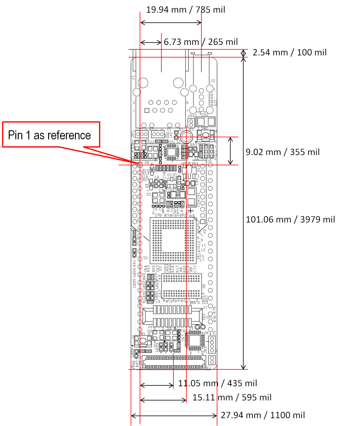
- Physical measures incl mounting hole and positions for the expansion connectors:

Compatibility with mbed LPC1768 module
The LPC4088 QuickStart Board has been designed to be as compatible as possible with the original LPC1768 mbed module pinning and general functionality. When studying the pin function pictures of the two boards there are many similarities in pinning and functionality. There are however some differences, as listed below:
- Physical size: The physical size of the module is changed from 54 x 26 mm to 101 x 28 mm (103.6 x 28 mm with connectors).
The original LPC1768 mbed module has a 40-pin, 0.1” pitch DIP package form factor while the LPC4088 QuickStart Board has a 44-pin, 0.1” pitch DIP package form factor with extensions in both short edge directions. - 4 extra pins: There are 4 extra expansion pins, two on each side.
- Pin 21 is reference ground of the analog signals.
- Pin 22 is an extra ground pin for improved grounding compared to the original LPC1768 mbed module.
- Pin 23 is a general digital pin. The on-board user push-button is connected to this pin. Pulling this pin low at reset will put the LPC4088 in ISP mode. This mode can be used to get in contact with a module where the application program has locked up the LPC4088, for example by accidentally initializing the PLLs wrong.
- P24 (together with P25-P30) provides an SD memory card interface. P24 can also be a general digital I/O pin.
- Powering: The LPC4088 QuickStart Board can be powered via the HDK micro-B USB connector, pin 2 (4.5-5.5V input) or via the trace connector (4.5-5.5V input). Note the maximum 5.5V input voltage limit on the LPC4088 QuickStart Board. This is lower upper voltage limit than the original LPC1768 mbed module (which accepts up to 9V input voltage).
For more information about the current consumption see the integration page.- The original LPC1768 mbed module can be powered via the on-board (HDK) mini-B USB connector or via an external 4.5-9V supply.
- The LPC4088 QuickStart Board has one 3.3V voltage generator that powers the on-board components and up to 300mA for external electronics.
- The LPC1768 QuickStart Board has one 3.3V voltage regulator for the on-board components and one for the external components (via pin P40).
- The LPC4088 QuickStart Board can also be powered by an external 3.3V supply (back-powered)
| Pin | LPC4088 QuickStart Board | LPC1768 mbed pin | LPC1768 mbed function |
|---|---|---|---|
| 1 | ground | 1 | ground |
| 2 | 4.5-5.5 Vin | 2 | 4.5-9.0 Vin |
| 43 | 4.5-5.5 Vout | 39 | 5V from USB. Total current from USB limited to about 450mA |
| 44 | 3.3V, <300mA, shared LDO, can be back-powered | 40 | 3.3V, <700mA, separate LDO |
- Pullup resistors: There are pullup resistors (1.5Kohm) on P31/P32 since these pins (P5.3 and P5.2) are always open-collector pins on the LPC4088. There are also pullup resistors (5Kohm) on P9/P10 since these pins (P0.0 and P0.1) can be open-collector pins on the LPC4088 if they are configured as I2C-pins. The 5Kohm pullup resistors on P9/P10 might be too weak for high I2C datarates or high capacitance I2C channels but for 100kbit/sec the resistors are enough. 2-3Kohm pullup resistors can be added externally, if needed.
- Ethernet interface: There is an on-board RJ45 Ethernet interface connector, with isolation transformers, on the LPC4088 QuickStart Board. The four Ethernet pins on the original LPC1768 mbed module have been used for other pins on the LPC4088 QuickStart Board.
- USB interfaces: The LPC4088 QuickStart Board has two USB interfaces. One interface (USB#1 on the LPC4088) is fixed to be a USB Host interface. There is an on-board USB-A connector for this interface. The second interface (USB#2 on the LPC4088) can be connected to an on-board micro-B USB connector for an USB Device interface. Alternatively the USB interface can be routed to the mbed edge pins (pin 35/36). This interface can be an USB Host or Device interface depending on how it is connected externally.
- Pin compatibility/functionality: (Show pictures of both LPC1768 and LPC4088 boards. Note that pin numbering is different between the modules since the LPC4088 QuickStart Board has four more pins.)
When comparing the LPC4088 QuickStart Board with the original LPC1768 mbed module there are some differences in pin functionality.
- There is a serial port on on P13/14 on the LPC1768 mbed. This serial port does not exist on the LPC4088 QuickStart Board.
- There is a serial port on P27/P28 on the LPC1768 mbed module. The tx-signal on this port has been moved to P37 on the LPC4088 QuickStart Board.
- The LPC4088 QuickStart Board has on-board Ethernet RJ45 connector. This frees up the four Ethernet pins on the original LPC1768 mbed module. These four pins are used for an SPI interface, a serial interface and an Alarm signal.
- The LPC4088 QuickStart Board has also some extra pin functions compared to the LPC1768.
- There is a second CAN interface on P9/P10 on the LPC4088 QuickStart Board.
- There is a third SPI interface on P32 (SCK), P38 (MISO) and P39 (MOSI).
- There is a SD memory card interface on P24-P30.
- P23 is an ISP enable pin.
- P40 carry the RTC ALARM signal.
- The HDK UART channel is available on P41/P42.
Current Consumption
The table below show example of current consumption for the LPC4088 QuickStart Board. The actual consumption really depend on the final application. The table below give you examples of what you can expect. Please note that the low consumption values are measured when the HDK is disabled (jumper JP3 is removed)
| Description | Current consumption |
|---|---|
| #1: Max | 400 mA |
| #2: while(true) {} | 135 mA |
| #3: Lowest (power-down) | 5 mA |
#1 Max
Maximum consumption occurs when all on-chip peripherals are enabled and external peripherals such as SDRAM and Ethernet are used. Please read section How to Design the Power Supply for more details.
#2 while(true) {}
The board has powered up running at 120 MHz and enters an infinite loop doing nothing.
#3 Lowest (power-down)
This example shows the lowest possible current consumption. External peripherals are powered-down, important pins (typically pins connected to external pull-down) are set to a defined state and the LPC4088 is set to power-down mode. The application below show how to achieve this low current consumption mode.
Import programapp_lowpwr
An application which show how to reach lowest current consumption for the LPC4088 QuickStart Board
18 comments on LPC4088 QuickStart Board - Hardware Information:
Please log in to post comments.


will the I2S and quad encoder pins be directly accessible on the quickstart ??