Campus Safety Bot
Purpose
Some locations require monitoring in order to determine the safety of the environment. For instance, on and near campus, street lights may go out, decreasing the safety of pedestrians and bikers in an area. In addition, lights may also stop working within buildings and labs. To monitor these environments regularly for light outages, a robot could optimally be used for automatic monitoring around campus, with the capability to send notifications for locations with dim or broken lights. To make a partial proof of concept to accomplish light monitoring, a Bluetooth-controlled robot with sonar sensing and an IMU for navigation to map an area's boundaries was developed.
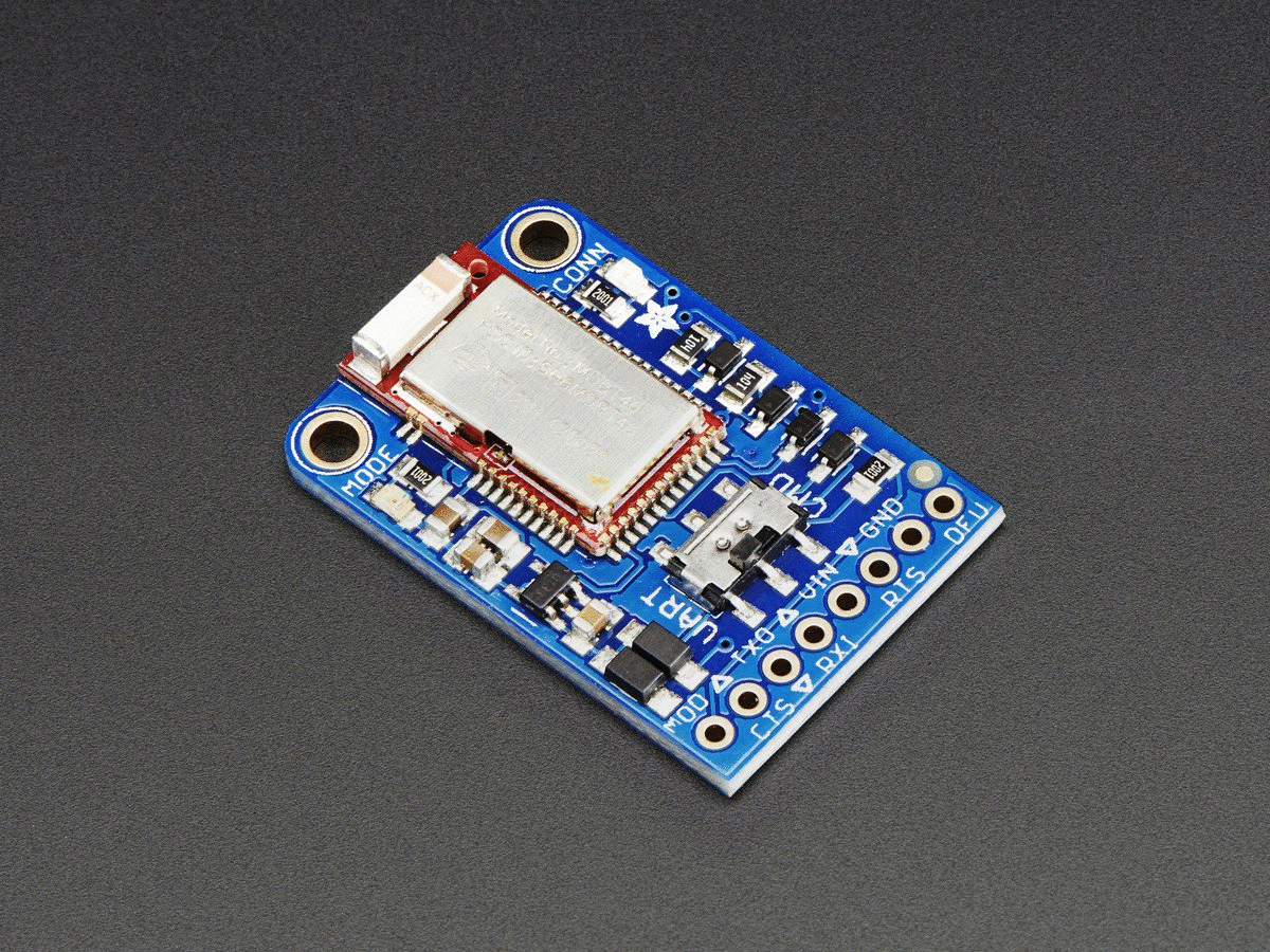
The robot is built using the shadow robot kit and the Mbed microcontroller for controlling the robot. Using Bluetooth direction pad controls(Bluefruit) on a phone that are sent to a Bluetooth receiver, the robot can move forward and turn left or right. Bluetooth is also used as a trigger for the sonar sensor, photo transistor, and IMU to start and terminate operation.
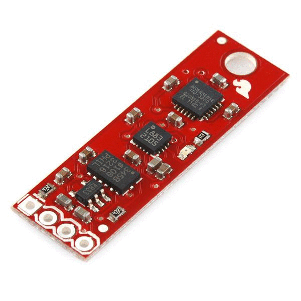
For determining the robot’s pose, odometry (dead reckoning using a timer and a known revolution speed for the DC motors) is used to determine relative position from the starting point, and an LSM9DS1 IMU is used for determining orientation through magnetic heading.
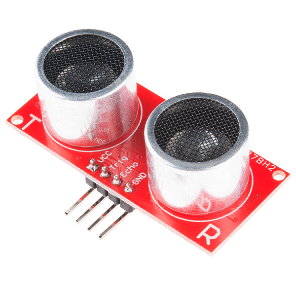
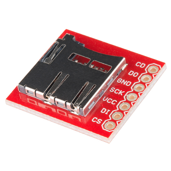
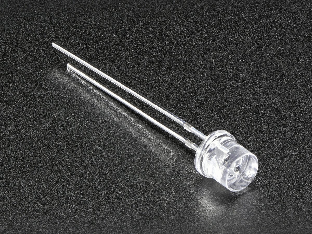
To collect data on the room boundaries and any obstacles, a sonar sensor faces outwards from one side of the robot, collecting distances periodically to determine the state of the outer boundary of the environment. A light sensor (CdS photo transistor) is used to collect the light intensity levels normalized to a range of 0.0 - 1.0 from darkness to full, direct sunlight around the room. The boundary distances, light intensity, and location data are stored in a text file on an 8 GB SD card. After navigating around the room, the SD card data can be loaded onto a computer and displayed graphically using Matlab code.
Assembling the Robot Body
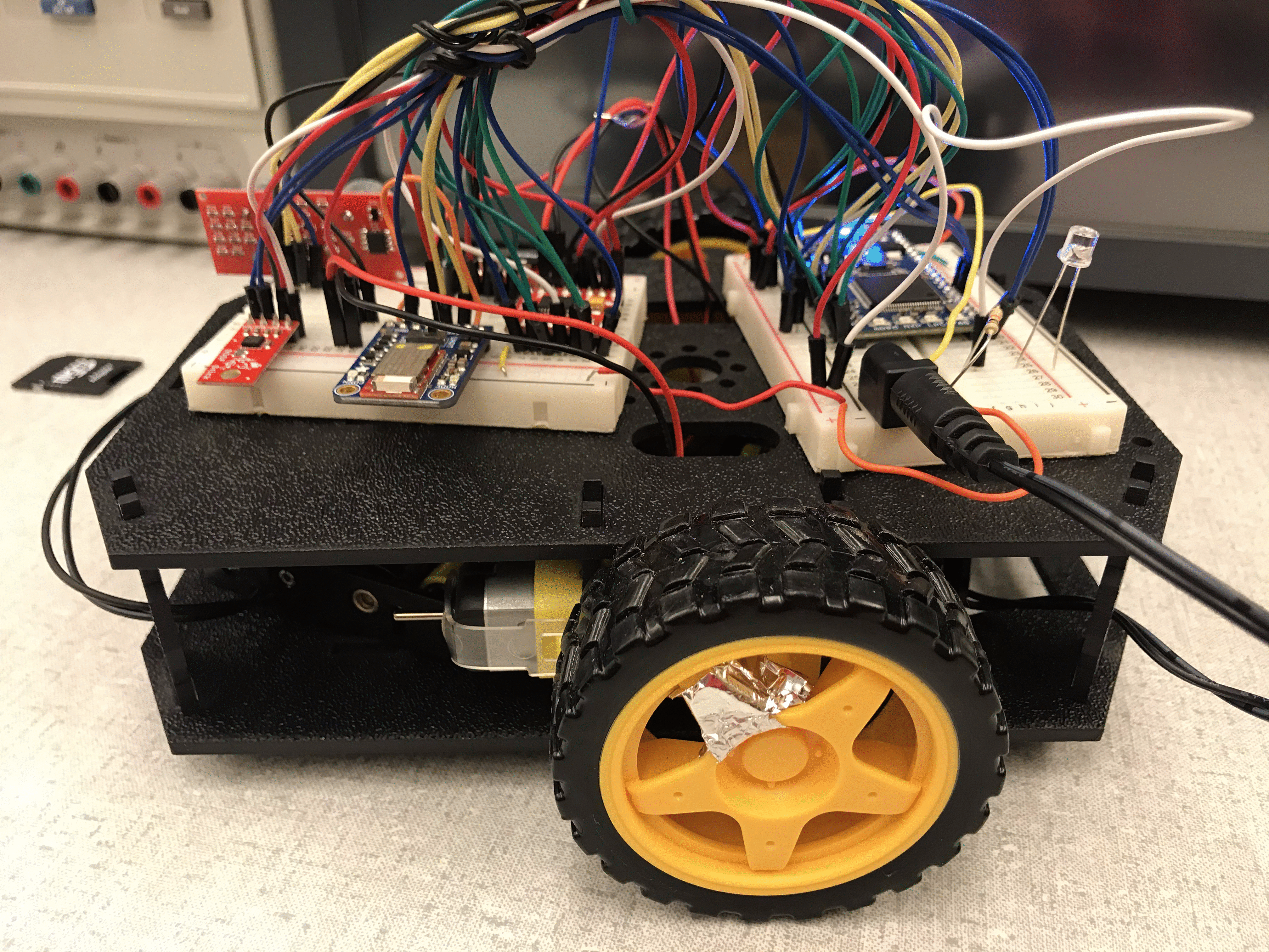
A shadow robot kit was assembled to create the robot body. A link to assembling the robot can be found on the sparkfun website. The following hardware and software is then used to create a fully functional robot.
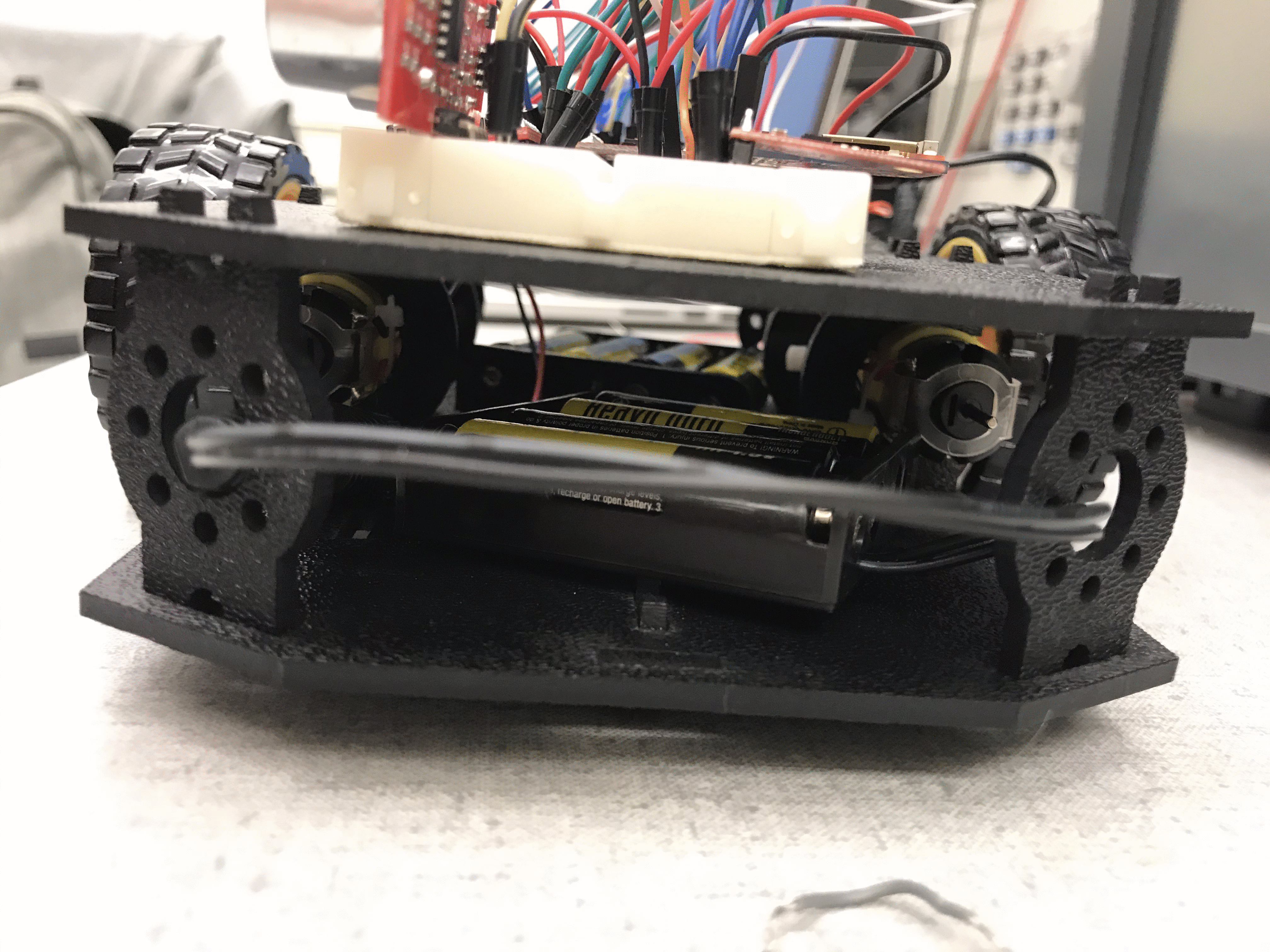
Battery
Two 5.0 - 6.5 voltage supplies are added to power the mbed and other hardware components. One of the voltage supplies is solely used to power the mbed, and the other is used to power both the Bluetooth and motors through the H-bridge. (If only one voltage supply is used, the mbed does not have enough power to run all processes and the system will reboot periodically as too much power is drawn.) Two barrel jack adapters are required for the two voltage supplies, with the grounds connected to the mbed ground, and one VCC connected to the mbed's Vin pin, and the other VCC connected to the H-bridge and Bluetooth receiver.
Odometry
Mbed's built-in timer (using the function timer()) is utilized to keep track of the elapsed time. The revolutions per minute (99-101 rpm at 0.4 PWM motor speed) was measured with a tachometer, and the diameter of the wheel (6.5 cm) was also measured using a ruler. These measured values are then used to estimated the distance travel by the robot when processing the collected data (distance = (linear speed) * time).
Wiring for Peripherals
Sonar
| mbed LPC1768 | HC-SR04 |
|---|---|
| Vu(5V) | Vcc |
| Gnd | Gnd |
| p11 | trig |
| p12 | echo |
Micro SD Card File System
| mbed LPC1768 | MicroSD |
|---|---|
| Vout(3.3V) | Vcc |
| Gnd | Gnd |
| p8 (DigitalOut cs) | CS |
| p7 (SPI sclk) | SCK |
| p6 (SPI miso) | DO |
| p5 (SPI mosi) | DI |
| nc | CD |
Bluetooth Receiver
| mbed LPC1768 | Adafruit BLE | Battery |
|---|---|---|
| Vin(3.3-16VDC) | 5-6.5V | |
| Gnd | Gnd | Gnd |
| nc | RTS | |
| Gnd | CTS | |
| p13 | TXO | |
| p14 | RXI |
Inertial Measurement Unit
| mbed LPC1768 | LSM9FS1 IMU |
|---|---|
| Vout(3.3V) | Vdd |
| Gnd | Gnd |
| p28(SDA) | SDA |
| p27(SCL) | SCL |
Photo Transistor
| mbed LPC1768 | Photo Transistor | |
|---|---|---|
| 3.3(V) | positive | |
| Gnd | 10k Resistor | |
| p18 | negative | 10k Resistor |
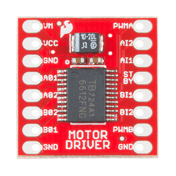
H-Bridge
| mbed LPC1768 | TB6612FNG | Battery | Motor L | Motor R |
|---|---|---|---|---|
| Vm | 5-6.5V | |||
| Vout(3.3V) | Vcc and STBY | |||
| Gnd | Gnd | Gnd | ||
| p21 | PWMA | |||
| p22 | PWMB | |||
| p15 | A11 | |||
| p16 | A12 | |||
| p20 | B11 | |||
| p19 | B12 | |||
| A01 | Pos | |||
| A02 | Neg | |||
| B01 | Pos | |||
| B02 | Neg |
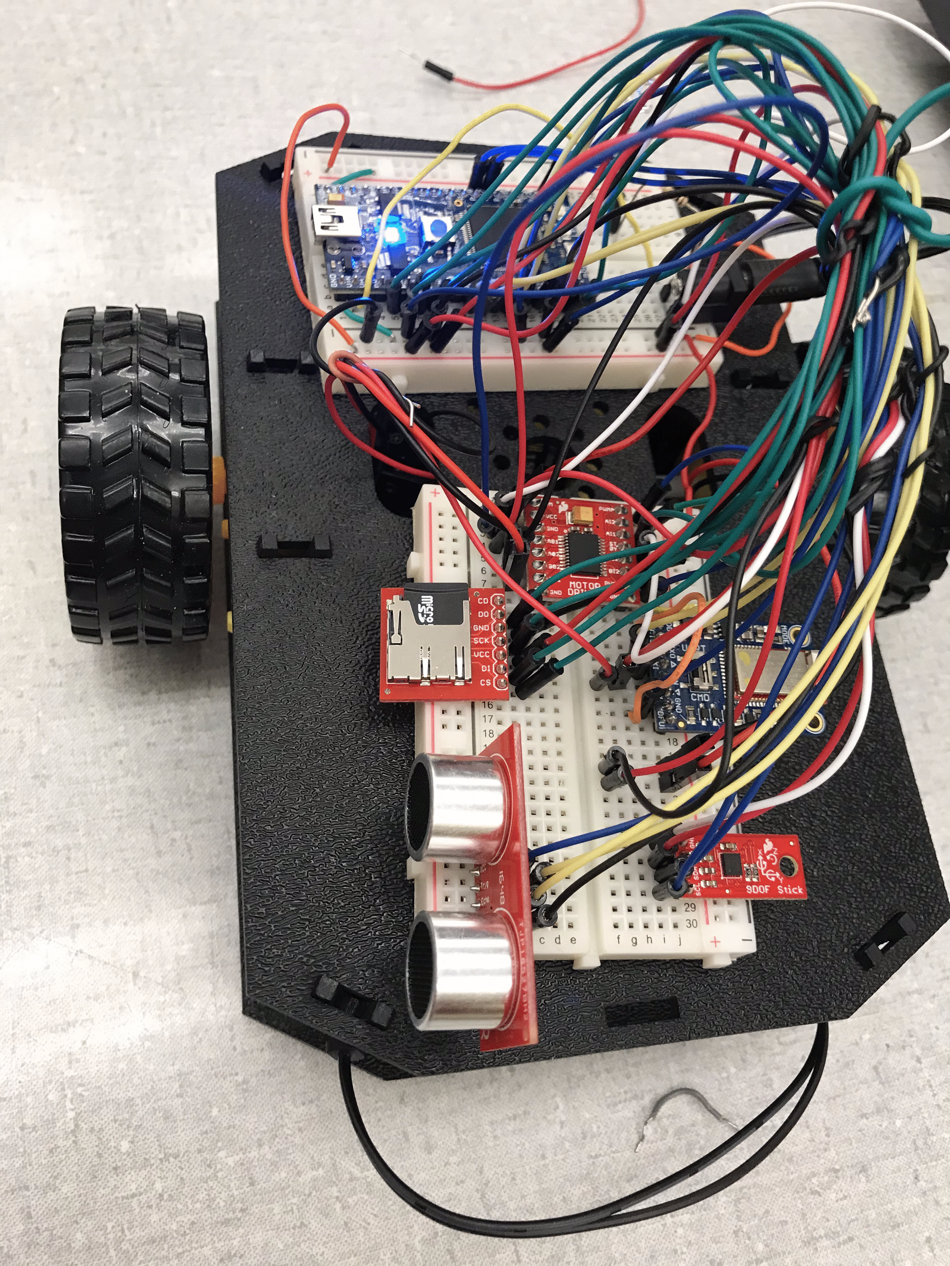
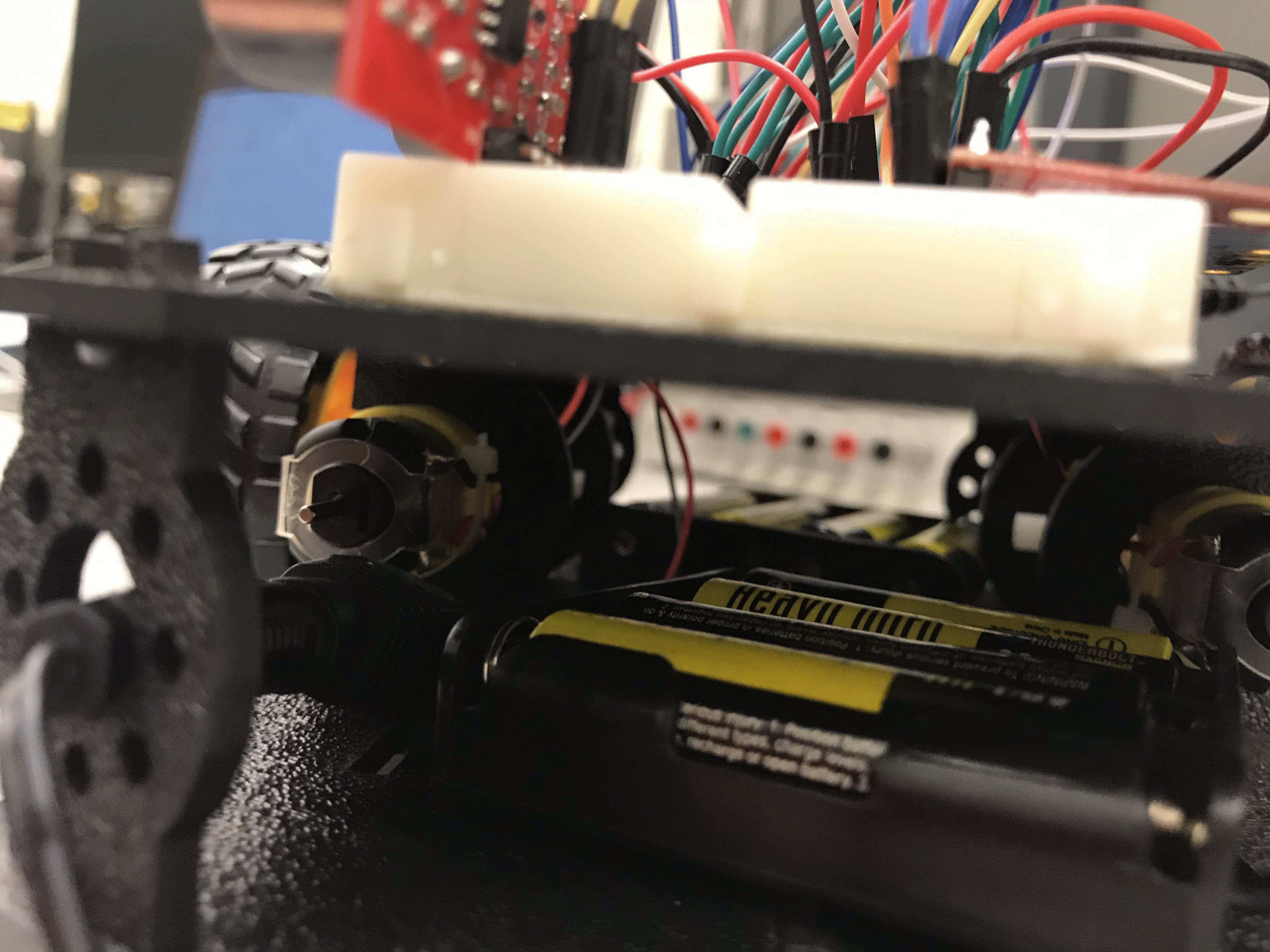
Assembled robot
Mbed Code Library
Import programCampus_Safety_Bot
ECE 4180 Final Project - Georgia Institute of Technology by LZ and EM
Mbed Shadow Robot Main Program
#include "mbed.h"
#include "ultrasonic.h"
#include "SDFileSystem.h"
#include <string>
#include "Motor.h"
#include "LSM9DS1.h"
#define PI 3.14159
#define DECLINATION -4.94 // Declination (degrees) in Atlanta,GA.
Serial pc(USBTX, USBRX);

DigitalOut led1(LED1);
DigitalOut led2(LED2);
DigitalOut led3(LED3);
DigitalOut led4(LED4);

//H-bridge
Motor m_left(p21, p15, p16); // pwm,fwd,rev pwmA
Motor m_right(p22, p19, p20); // pwm,fwd,rev

//Photo transistor
AnalogIn photocell(p18);

//Timer
Timer t; //t.start(), t.stop(), t.read()

//SD Card
SDFileSystem sd(p5, p6, p7, p8, "sd");

RawSerial  Bluetooth(p13,p14); // tx, rx

//Global variables for bluetooth control
bool sonarOn = false; //Indicates when sonar is taking measurements
char heading = '0'; //Indicates rough direction of the robot; 'f' = forward, 'l' = left, 'r' = right, 'b' = backwards, '0' = not moving
bool running = true; //Keeps main while loop going


//Code for interrupt routine for Bluetooth input
enum statetype {start = 0, got_exclm, got_B, got_one, got_two, got_three, got_five, got_six, got_seven, got_eight, got_11, got_21, got_31, got_51, got_61, got_71, got_81};
statetype state = start;
//Interrupt routine to parse message with one new character per serial RX interrupt
void parse_message()
{
    switch (state)
    {
        case start:
            if (Bluetooth.getc()=='!')
            {
                //led2 = 1;
                state = got_exclm;
            }
            else state = start;
            break;
        case got_exclm:

            if (Bluetooth.getc() == 'B')
            {
                state = got_B;
            }
            else state = start;
            break;
        case got_B:
        {
            char recv = Bluetooth.getc();
            if (recv == '1') state = got_one;
            else if (recv == '2') state = got_two;
            else if (recv == '3') state = got_three;
            else if (recv == '5') state = got_five;
            else if (recv == '6') state = got_six;
            else if (recv == '7') state = got_seven;
            else if (recv == '8') state = got_eight;
            else state = start;
        }
        break;
        case got_one:
            if (Bluetooth.getc() == '1')
            {
                //Make sure motors are stopped
                m_left.speed(0.0);
                m_right.speed(0.0);
                sonarOn = false;
                heading = '0';
                running = false;
            }
            else state = start;
            break;
        case got_two: //Stop everything
            if (Bluetooth.getc() == '1')
            {

            }
            else state = start;
            break;
        case got_three: //currently unimplemented
            if (Bluetooth.getc() == '1')
            {

            }
            else state = start;
            break;
        case got_five: //up arrow pressed
        {
            char recv = Bluetooth.getc();
            if (recv == '1') //Button pressed or held
            {
                sonarOn = true;
                heading = 'f';
                m_left.speed(0.4);
                m_right.speed(0.4);
            }
            else if (recv == '0') //Button released
            {
                //sonarOn = false;
                heading = '0';
                m_left.speed(0.0);
                m_right.speed(0.0);
            }
            else state = start;
        }
            break;
        case got_six: //down arrow pressed
        {
            char recv = Bluetooth.getc();
            if (recv == '1') //Button pressed or held
            {
                sonarOn = true;
                heading = 'b';
                m_left.speed(-0.4);
                m_right.speed(-0.4);
            }
            else if (recv == '0')
            {
                //sonarOn = false;
                heading = '0';
                m_left.speed(0.0);
                m_right.speed(0.0);
            }
            else state = start;
        }
            break;
        case got_seven: //turn left
        {
            char recv = Bluetooth.getc();
            //sonarOn = false;
            if (recv == '1')
            {
                heading = 'l';
                m_left.speed(-0.3);
                m_right.speed(0.3);
            }
            else if (recv == '0')
            {
                heading = '0';
                m_left.speed(0.0);
                m_right.speed(0.0);
            }
            else state = start;
        }
            break;
        case got_eight: //turn right
        {
            char recv = Bluetooth.getc();
            //sonarOn = false;
            if (recv == '1')
            {
                heading = 'r';
                m_left.speed(0.3);
                m_right.speed(-0.3);
            }
            else if (recv == '0')
            {
                heading = '0';
                m_left.speed(0.0);
                m_right.speed(0.0);
            }
            else state = start;
        }
            break;

        default:
            Bluetooth.getc();
            state = start;
    }
}

//To see serial output on Mac, run ls /dev/tty.usbmodem* once the mbed is connected
//to find its location. Then run screen <mbed location> to see serial output.
int Left[1000];
float Time[1000];
char Head[1000];
float Light[1000];
float Mag[1000];
int j = 0;
int k = 0;
volatile bool startTime = false;

void distL(int distance)
{
    if (sonarOn && startTime)
    {
        Left[j] = distance;
        Time[j] = t.read();
        Head[j] = heading;
        Light[j] = (float)photocell;
        j++;
        printf("Distance %i mm, Time %f s, Light %0.3f ,Heading %c \r\n", distance, t.read(), (float)photocell, heading);//code here to execute when distance changes
    }
}
//IMU
void printAttitude(float ax, float ay, float az, float mx, float my, float mz)
{
    if(sonarOn && startTime)
    {
    float roll = atan2(ay, az);
    float pitch = atan2(-ax, sqrt(ay * ay + az * az));
// touchy trig stuff to use arctan to get compass heading (scale is 0..360)
    mx = -mx;
    float heading;
    if (my == 0.0)
        heading = (mx < 0.0) ? 180.0 : 0.0;
    else
        heading = atan2(mx, my)*360.0/(2.0*PI);
    //pc.printf("heading atan=%f \n\r",heading);
    heading -= DECLINATION; //correct for geo location
    if(heading>180.0) heading = heading - 360.0;
    else if(heading<-180.0) heading = 360.0 + heading;
    else if(heading<0.0) heading = 360.0  + heading;

    // Convert everything from radians to degrees:
    //heading *= 180.0 / PI;
    pitch *= 180.0 / PI;
    roll  *= 180.0 / PI;

    //pc.printf("Pitch: %f,    Roll: %f degress\n\r",pitch,roll);
    pc.printf("Magnetic Heading: %f degress\n\r",heading);
    wait(0.3);
    Mag[k] = heading;
    k++;
    }
}
//sample 10 times every 3 seconds
ultrasonic mu_L(p11, p12, .3, 1, &distL);    //Set the trigger pin to D8 and the echo pin to D9
                                        //have updates every .1 seconds and a timeout after 1
                                        //second, and call dist when the distance changes

int main()
{
    LSM9DS1 IMU(p28, p27, 0xD6, 0x3C);
    led = 0.0
    IMU.begin();
    if (!IMU.begin()) {
        pc.printf("Failed to communicate with LSM9DS1.\n");
    }
    IMU.calibrate(1);
    IMU.calibrateMag(0);
    led1 = 1.0;
    wait(0.5);
    led1 = 0.0;
    //t.start(); //start timer
    mu_L.startUpdates(); //start measuring the distance with sonar sensor
    Bluetooth.attach(&parse_message,Serial::RxIrq); //attach bluetooth interrupt

    while(running)
    {
         mu_L.checkDistance();     //call checkDistance() as much as possible, as this is where
                                //the class checks if dist needs to be called.
        //Start the timer only once sonar has turned on and the timer has not been previously started
        while(!IMU.tempAvailable());
        IMU.readTemp();
        while(!IMU.magAvailable(X_AXIS));
        IMU.readMag();
        while(!IMU.accelAvailable());
        IMU.readAccel();
        while(!IMU.gyroAvailable());
        IMU.readGyro();
        printAttitude(IMU.calcAccel(IMU.ax), IMU.calcAccel(IMU.ay), IMU.calcAccel(IMU.az), IMU.calcMag(IMU.mx),
                      IMU.calcMag(IMU.my), IMU.calcMag(IMU.mz));
        if (sonarOn && !startTime)
        {
            startTime = true;
            t.start();
        }
    }

    //Store values into SD card
    //Open a new file to store the data
    mkdir("/sd/mydir", 0777);
    FILE *left = fopen("/sd/mydir/left.txt", "w");
    if(left == NULL) //If there is an error in opening the file, throw error
    {
        error("Could not open file left for write\n");
    }
    fprintf(left, "sonar, \t time, \t light, \t heading \n");
    //Loop through array values and store into each line of text
    for (int i=0; i<1000; i++)
    {
        fprintf(left, "%i, %0.4f, %0.4f, %0.4f, %c \n", Left[i], Time[i],Light[i] , Mag[i], Head[i]);
    }
    //Close file
    fclose(left);
}
Demo of the mbed code on the assembled robot
Data Processing
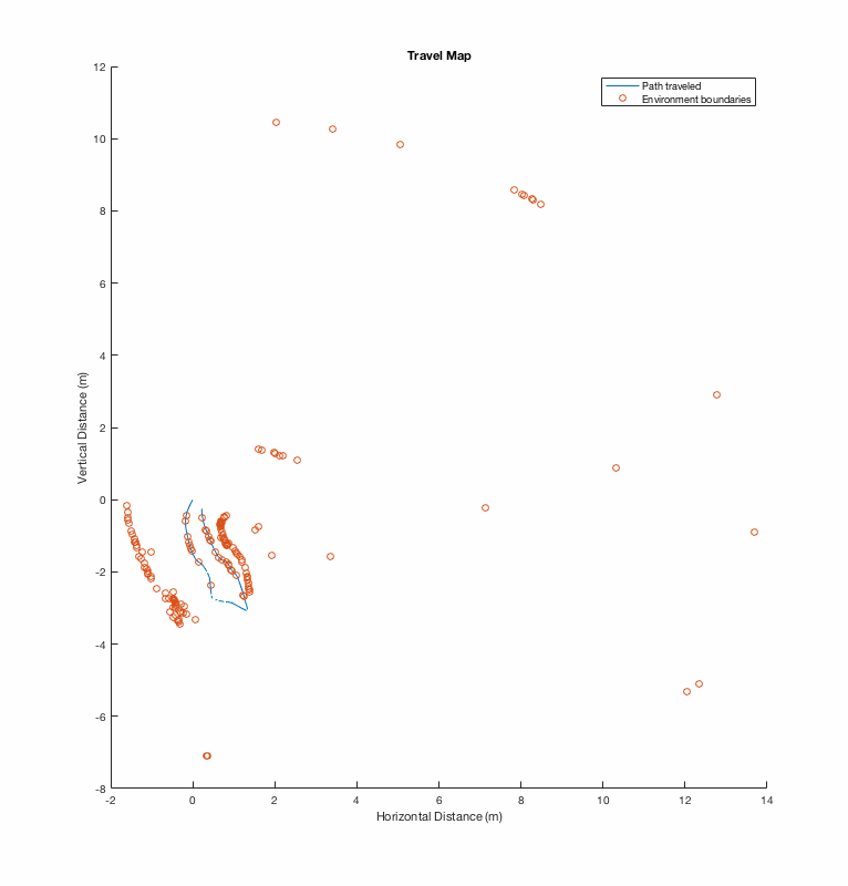
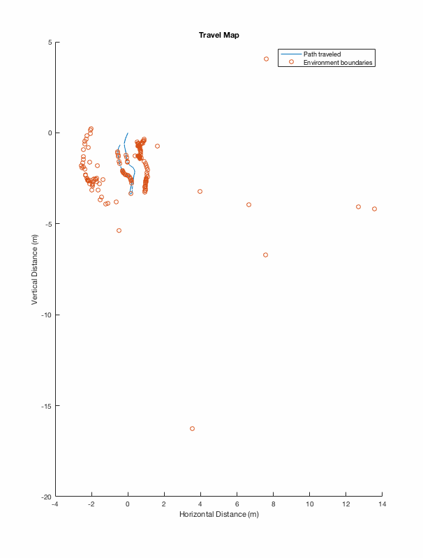
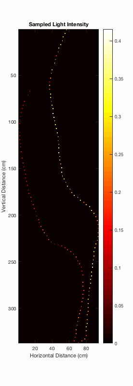
After the data is collected, the SD card can be removed from the robot and inserted into a computer using an adapter. A MATLAB script (included below) then parses the saved text file of data directly from the SD card and creates two plots: one for the path of the robot and sampled boundary points from the sonar, and another for the light intensity along the robot's traveled path.
Matlab Data Processing
%Code for displaying mapping information and light intensity from mbed
%robot output
%File is named left.txt when SD card is plugged in

%Read file and extract information
textfile = fopen('/Volumes/SDCARD/mydir/left.txt', 'r'); %Open text file for reading
%Variables that store the information from the text file
datacell = textscan(textfile, '%f  %f  %f %f %c', 'Delimiter', ',', 'CommentStyle', 'sonar');
fclose(textfile);

%Parse extracted information for desired data
%First index has sonar, second has time, third light, fourth IMU heading
%angle, fifth rough heading based on Bluetooth
nsamples = length(datacell{1}); %Determine number of samples
%Variables for plotting
pathx = NaN(1, nsamples+1);
pathy = NaN(1, nsamples+1);
sonarx = NaN(1, nsamples+1); %Sonar variables have useless NaN as the first element to match with the robot path more easily
sonary = NaN(1, nsamples+1);
light = NaN(1, nsamples);
pathxi = 0; pathyi = 0; %Set initial path location to (0,0);
pathx(1) = pathxi; pathy(1) = pathyi; %Record previous value for variables
timei = 0; %Set starting time to 0 s
angle = 90; %Angle of heading in degrees, with 0 being forward
sonarangle = 180;
for n = 1:nsamples %Go through all data and calculate necessary variables plots
    if datacell{1}(n) ~= 0 && datacell{5}(n) ~= '0'
        dt = datacell{2}(n) - timei; %Change in time
        dist = dt*99/60*6.5*10^-2; %Distance (magnitude) traveled by robot between ith and (i+1)th sample
        %Determine direction traveled and assign angle for sonar
        %appropriately
        switch datacell{5}(n)
            case 'f' %Traveling forward
                %angle = 90;
                angle = datacell{4}(n);
                sonarangle = angle + 90;
            case 'l' %Traveling left
                %angle = 180;
                angle = datacell{4}(n);
                sonarangle = angle + 90;
            case 'r' %Traveling right
                %angle = 0;
                angle = datacell{4}(n);
                sonarangle = angle + 90;
            case 'b' %Traveling backwards/in reverse
                %angle = 270;
                angle = datacell{4}(n);
                sonarangle = angle - 90;
            %otherwise
            %    angle = 0;
        end
        %Update traveled path and sonar distances
        pathx(n+1) = pathxi + dist*cosd(angle);
        pathy(n+1) = pathyi + dist*sind(angle);
        sonarx(n+1) = pathx(n+1) + datacell{1}(n)/1000*cosd(sonarangle);
        sonary(n+1) = pathy(n+1) + datacell{1}(n)/1000*sind(sonarangle);
        %Update ith/previous variable record
        pathxi = pathx(n+1);
        pathyi = pathy(n+1);
        %Store light into array
        light(n) = datacell{3}(n);
    end
    timei = datacell{2}(n); %Update ith/previous time so odometry accurate
end

%Plot the path and the barrier
figure;
hold on;
plot(pathx, pathy);
scatter(sonarx, sonary);
hold off;
title('Travel Map');
legend('Path traveled','Environment boundaries');
xlabel('Horizontal Distance (m)');
ylabel('Vertical Distance (m)');

%Plot the light intensity with the path as an image
image = zeros(ceil((max(pathx) - min(pathx))*100 + 1), ceil((max(pathy) - min(pathy))*100 + 1)); %Converts to cm before making zero array
%Go through all samples to assign light intensities to image pixels
for n = 1:nsamples
    if ~isnan(pathx(n+1)) %Record light intensity only if coordinate actually has value
        image(ceil((pathx(n+1)+abs(min(pathx)))*100 + 1), ceil((pathy(n+1)+abs(min(pathy)))*100 + 1)) = light(n); %Assign point on path with respectively sampled light intensity
    end
end

%Display image
figure;
imagesc(flipud(image')); %Flip the transpose vertically so the origin is on the bottom left, x axis points right, and y axis points up
title('Sampled Light Intensity');
xlabel('Horizontal Distance (cm)');
ylabel('Vertical Distance (cm)');
colormap('hot');
colorbar;
Matlab Code
Matlab Processed Graph
by Elisha Mang and Louise Zhuang
Please log in to post comments.

