Accelerometer Controlled Rover(Wireless)
Accelerometer Controlled Rover(Wireless)
by Shubhojit Chattopadhyay & Pratik Chatterjee
Introduction
This Project demonstrates the use of an ADXL 345 Accelerometer to control a robot wirelessly using 2 Xbee Modules. It consists of 2 units: A base unit having the accelerometer, mbed and a xbee module and a remote unit having the robot(controlled by 2 dc motors through 2 H-bridges), mbed and a xbee module. The sampled tilt values of the accelerometer is communicated wirelessly by the xbee module on the base unit and is picked up by the xbee module on the remote unit and is fed to the dc motors to move the robot forward or reverse. We have only considered the movement of the accelerometer in one direction(i.e X axis).
Check at the bottom of this page for links to all the modules used in References.
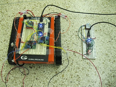
Image
The remote unit is on the left and the base unit is on the right.

Figures and Connections


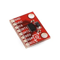
Connections between mbed and ADXL345
| MBED pins | ADXL 345 pins |
|---|---|
| Vout | Vcc |
| Gnd | Gnd |
| p5 | SDA |
| p6 | SDO |
| p7 | SCL |
| p8 | CS |
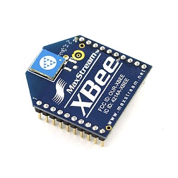
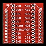
Connections between mbed and xbee Module
| MBED pins | Xbee Module pins |
|---|---|
| 3.3V | Vcc |
| serial rx(p10) | Dout |
| serial tx(p9) | Din |
| Digitalout pin(eg.p11,p8) | RST |
| Gnd | Gnd |
Connections between mbed and H-bridge
| MBED pins | H-bridge |
|---|---|
| pwm(p22,23) | PWM |
| Digitalout pin(fwd) | INa |
| Digitalout pin(rev) | INb |
Code
Base Unit
The base unit consists of a mbed , ADXL345 accelerometer and a xbee module.
//Base Unit containing the accelerometer and the Xbee Module
#include "mbed.h"
 #include "ADXL345.h"

 ADXL345 accelerometer(p5, p6, p7, p8);
 Serial pc(USBTX, USBRX);

Serial xbee1(p9, p10);
DigitalOut rst1(p11);


DigitalOut myled(LED3);//Create variable for Led 3 on the mbed

int main() {

    // reset the xbees (at least 200ns)
    rst1 = 0;
   // rst2 = 0;
    wait_ms(1);
    rst1 = 1;
  //  rst2 = 1;
    wait_ms(1);

     int readings[3] = {0, 0, 0};

     pc.printf("Starting ADXL345 test...\n");
     pc.printf("Device ID is: 0x%02x\n", accelerometer.getDevId());

     //Go into standby mode to configure the device.
     accelerometer.setPowerControl(0x00);

     //Full resolution, +/-16g, 4mg/LSB.
     accelerometer.setDataFormatControl(0x0B);

     //3.2kHz data rate.
     accelerometer.setDataRate(ADXL345_3200HZ);

     //Measurement mode.
     accelerometer.setPowerControl(0x08);

    while(1) {

             wait(0.5);

         accelerometer.getOutput(readings);

         //13-bit, sign extended values.
         pc.printf("%f, %f, %f\n\r", (float)readings[0]/65535, (float)readings[1]/65535, (float)readings[2]/65535);

        if ((float)readings[1]/65535 > 0.5)
        xbee1.putc('C'); //Forward
        if ((float)readings[1]/65535 < 0.5)
        xbee1.putc('D'); //Reverse
        myled = 1;
             wait_ms(100);
             myled=0;
              wait_ms(100);

    }
}
Import programxbee_base
Code for Base Module
Remote Unit
The Remote unit consists of a mbed ,a xbee module and H-bridge controlled 2 dc motors.
//Robot Unit with the Xbee module

#include "mbed.h"
#include "Motor.h"

Serial xbee2(p9, p10);
DigitalOut rst2(p8);

Serial pc(USBTX, USBRX);

DigitalOut myled2(LED3);
DigitalOut myled1(LED4);

Motor m1(p23, p11, p12); // pwm, fwd, rev //lEFT MOTOR
Motor m2(p22, p14, p15); // pwm, fwd, rev //rIGHT MOTOR

Motor m3(p23, p12, p11); // pwm, rev, fwd
Motor m4(p22, p15, p14); // pwm, rev, fwd
int main() {
    char temp = '0';

    // reset the xbees (at least 200ns)
   // rst1 = 0;
    rst2 = 0;
    wait_ms(1);
    //rst1 = 1;
    rst2 = 1;
    wait_ms(1);

     for (float s= -1.0; s < 1.0 ; s += 0.01) {
     while(1) {
     temp = xbee2.getc();
     if(temp == 'C'){  //FORWARD
        m1.speed(s);
        m2.speed(s);
        wait(0.02);
        }

         if(temp == 'D'){ //REVERSE
        m3.speed(s);
        m4.speed(s);
        wait(0.02);
        }

                myled1 = 1;
                wait_ms(1);
                myled1 = 0;
                myled2 =1;

   }
  }
}
Import programxbee_robot
Code For the Remote Module
Video
The following video was taken outside the ECE 4180 lab at Georgia Tech.
References
1 comment on Accelerometer Controlled Rover(Wireless):
Please log in to post comments.

what is configuration mode of both xbees?