ZB Coord API for XBee: This XBee library drives Digi XBee ZB Modules in API Operation mode. Most commands include remote communication's are supported by the functions of this library. You can control XBee devices through the API software modules in this, without using any AT commands. Please refer to the following page and some of sample codes:
Dependents: sample02_sw xbee_aging sample01_led sample04_sens
XBee library 'ZB Coord API'

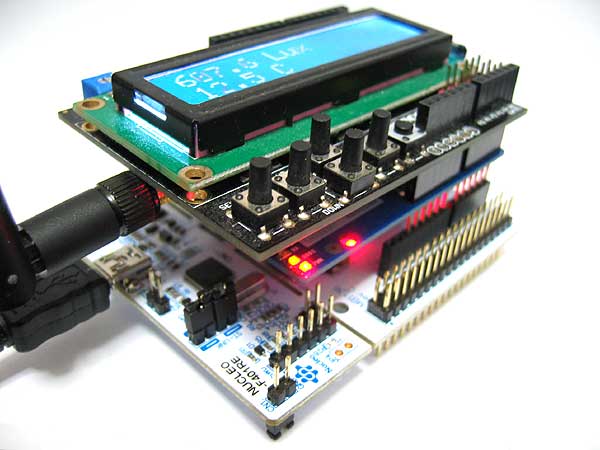
Nucleo Board + Arduino Wireless Shield + XBee ZB Module + LCD
This XBee liblary is developed for Digi XBee ZB Modules on Nucleo F401RE Micro Computer Board through Arduino Wireless Shield.
Quote:
When you will use this liblary for anything other than Nucleo microcomputer board, please change the 4th line of xbee/xbee.cpp. The above code is only for STM32 Nucleo board.
- RawSerial _xbee_serial(SERIAL_TX, SERIAL_RX);

Hardware Jumper Settings
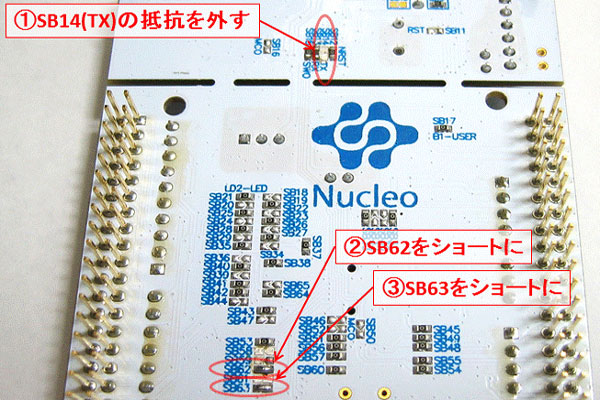
The hardware soldering jumper setting for the serial ports is necessary for Nucleo board.
- Set OPEN for SB14(TX)
- Set SHORT jumper for SB62
- Set SHORT jumper for SB63

Examples
Sample Code 01 LED
An XBee ZB Coordinator on a Nucleo Board controls LEDs on the other XBee ZB device.
#include "xbee.h"
DigitalOut myled(LED1);

int main(){
    // Please set MAC Address to access your remote XBee device.
    byte dev_gpio[]   = {0x00,0x13,0xA2,0x00,0x40,0x30,0xC1,0x6F};

    myled = 1;                          // set Higher Level(3.3V) for LED port on NUCLEO
    xbee_init( 0 );                     // Initialize XBee COM Port Settings
    xbee_atnj( 0xFF );                  // Enable Network Join
    myled = 0;                          // set Lower Level(0.0V) for LED port on NUCLEO

    while(1){
        myled = 1;                      // set Higher Level(3.3V) for LED port on NUCLEO
        xbee_gpo(dev_gpio,11,1);        // set H Level for GPO port 11 on remote xbee
        xbee_gpo(dev_gpio,12,1);        // set H Level for GPO port 12 on remote xbee
        wait(1);
        myled = 0;                      // set Lower Level(0.0V) for LED port on NUCLEO
        xbee_gpo(dev_gpio,11,0);        // set L Level for GPO port 11 on remote xbee
        xbee_gpo(dev_gpio,12,0);        // set L Level for GPO port 12 on remote xbee
        wait(1);
    }
}
http://mbed.org/users/bokunimowakaru/code/sample01_led/
Sample Code 02 Switch
To push buttons (or switches) on an XBee ZB device report the conditions of input ports on it to a Nucleo board, and display them on a LCD.
#include "xbee.h"
#include "TextLCD.h"
TextLCD lcd(PA_9, PC_7, PB_5, PB_4, PB_10, PA_8); // rs, e, d4-d7

int main(){
    byte data;
    int i;
    XBEE_RESULT xbee_result;
    byte dev_gpio[]   = {0x00,0x13,0xA2,0x00,0x40,0x30,0xC1,0x6F};

    lcd.cls(); lcd.printf("Sample 2 SW");
    xbee_init( 0x00 );
    lcd.cls(); lcd.printf("ATNJ");
    xbee_atnj( 0xFF );
    lcd.cls(); lcd.printf("gpio init");
    xbee_gpio_init(dev_gpio);           // Send GPIO mode settings to remote device.
    lcd.cls(); lcd.printf("DONE");

    while(1){
        data = xbee_rx_call( &xbee_result );
        if( xbee_result.MODE == MODE_GPIN){     // When a GPIO packet is recieved,
            lcd.cls();
            for( i=7; i>=0 ; i--) lcd.printf( "%c",(char)( (int)'0' + ((data>>i) & 0x01) ) );
                                        // Display the recieved data.
        }
    }
}
http://mbed.org/users/bokunimowakaru/code/sample02_sw/
Sample Code 04 Sensor
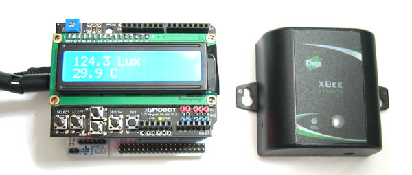
Measured results of an XBee wireless sensor device are displayed a LCD on Nucleo board with an XBee coordinator which is in API mode.
#include <xbee.h>
#include "TextLCD.h"
#define FORCE_INTERVAL  100
TextLCD lcd(PA_9, PC_7, PB_5, PB_4, PB_10, PA_8); // rs, e, d4-d7
byte dev_sens[8];   // IEEE Address

int main(){
    int i;
    int dev_en = 0;                 // Device Detection Flag
    XBEE_RESULT xbee_result;            // Stracture for recieved data
    int trig=0;
    float value;

    lcd.cls(); lcd.printf("Sample 4 SENS");
    xbee_init( 0x00 );
    lcd.cls(); lcd.printf("Searching:SENSOR");
    if( xbee_atnj(10) ){                // Enable Network Join during 10 seconds.
        lcd.cls(); lcd.printf("Found a device");
        xbee_from( dev_sens );          // Get address of remote device.
        dev_en = 1;
        xbee_gpio_config( dev_sens, 1 , AIN ); // Analog Input mode to port 1 on remote device
        xbee_gpio_config( dev_sens, 2 , AIN ); // Analog Input mode to port 2 on remote device
    }else{
        lcd.cls(); lcd.printf("Failed:no dev.");
    }
    wait(1);
    lcd.cls();

    while(1){
        if(dev_en){
            if(trig<=0){
                lcd.locate(12,0); lcd.printf("Trig"); wait(0.1);
                xbee_force(dev_sens);           // Send a request command to remote device.
                trig = FORCE_INTERVAL;
                lcd.locate(12,0); lcd.printf("    ");
            }
        }else{
            lcd.cls(); lcd.printf("Waiting for XBee");
            wait(0.5);
            lcd.cls();
        }
        trig--;

        xbee_rx_call( &xbee_result );       // Check a recieved packet.
        switch( xbee_result.MODE ){         // Check the packet type.
            case MODE_RESP:                 // the responce for the request in xbee_force().
            case MODE_GPIN:                 // Report data from remote xbee device.
                if( bytecmp( dev_sens , &(xbee_result.FROM[0]) ,8 ) == 0 && xbee_result.STATUS == STATUS_OK ){
                    value = xbee_sensor_result( &xbee_result, LIGHT);
                    lcd.locate(0,0); lcd.printf( "%.1f Lux   ",value);
                    value = xbee_sensor_result( &xbee_result, TEMP);
                    lcd.locate(0,1); lcd.printf( "%.1f C   ",value);
                }
                break;
            case MODE_IDNT:             // Commissioning Button Report is recieved.
                lcd.cls(); lcd.printf("found a new dev");
                for( i=0;i<8;i++ ) dev_sens[i]=xbee_result.FROM[i];
                                        // Save MAC address of reported device.
                dev_en = 1;             // Flag on (A sensor is detected.)
                trig = 0;
                xbee_gpio_config( dev_sens, 1 , AIN ); // Set Analog Mode to port 1 on remote XBee
                xbee_gpio_config( dev_sens, 2 , AIN ); // Set Analog Mode to port 2 on remote XBee
                lcd.cls();
                break;
            default:
                break;
        }
    }
}
http://mbed.org/users/bokunimowakaru/code/sample04_sens/
xbee.h
- Committer:
- bokunimowakaru
- Date:
- 2014-09-23
- Revision:
- 0:d72830877d98
- Child:
- 5:6ce45b34d3f0
File content as of revision 0:d72830877d98:
#define ARM_MBED
//#define ARM_MBED
/*********************************************************************
本ソースリストおよびソフトウェアは、ライセンスフリーです。
利用、編集、再配布等が自由に行えますが、著作権表示の改変は禁止します。

							   Copyright (c) 2010-2014 Wataru KUNINO
							   http://www.geocities.jp/bokunimowakaru/
*********************************************************************/

/*********************************************************************
インポート処理				   ※ライブラリ xbee.inoに必要な宣言です
*********************************************************************/
#ifndef XBEE_H
#define XBEE_H

#ifndef LCD_TYPE_H
	#define LCD_TYPE_H
	#ifdef ARDUINO
		#if defined(__AVR_ATmega32U4__)
			#define LEONARDO	// Arduino LEONARDを使用する場合に自動的に定義されます。
		#endif
	//	#define LCD_H		// 本ライブラリ動作を液晶表示する場合に定義する
	//	#define ADAFRUIT	// 使用する液晶が Adafruit LCD Sheild の時に定義する
	#else // H8 or ARM or PC
		#ifndef ARM_MBED	// H8 or PC
			#define LCD_H
		#endif
	#endif
//	#define XBEE_WIFI	// XBee Wi-Fiを使用するときに定義する
//	#define XBEE_WIFI_DEBUG
//	#define LITE		// ライトモード(メモリ節約・機能制限)の時に定義する
	#define EASY_GPI	// xbee_gpi関数(リモートGPIO)を使用するときに定義する
	#define EASY_ADC	// xbee_adc関数(リモートADC)を使用するときに定義する
#endif

#ifndef XB_IMPORT_H
	#ifdef H3694
		#ifndef __3694_H__
			#include <3694.h>
		#endif
		#ifdef LCD_H
			#ifndef LCD_ROW_1
				#include "lcd_h8.c"
			#endif
		#endif
		/*	// lcd_h8ライブラリの関数
		void lcd_delay(unsigned int data);
		void lcd_toggle_E(void);
		void lcd_cls(void);
		void lcd_home(void);
		void lcd_control(unsigned char disonoff, unsigned char curonoff, unsigned char curblink);
		void lcd_goto(unsigned char mesto);
		void lcd_shift(unsigned char data);
		void lcd_putch(char data);
		void lcd_putstr(const char *data);
		void lcd_disp_bin(unsigned char x);
		void lcd_disp_hex(unsigned char i);
		void lcd_disp_1(unsigned int x);
		void lcd_disp_2(unsigned int x);
		void lcd_disp_3(unsigned int x);
		void lcd_disp_5(unsigned int x);
		void lcd_init(void);
		*/
	#elif ARDUINO
		//	#include <inttypes.h>
		#include "Arduino.h"
		//	#include "WProgram.h"	// #if ARDUINO < 100
		#ifdef LCD_H
			#ifndef ADAFRUIT
				// 通常のキャラクタLCDの場合
				#include <LiquidCrystal.h>
			#else
				// Adafruit I2C接続LCDの場合(Adafruit_RGBLCDShieldライブラリが必要)
				#include <Wire.h>
				#include <Adafruit_MCP23017.h>
				#include <Adafruit_RGBLCDShield.h>
			#endif
		#endif
		#ifdef XBEE_WIFI
			#include <SPI.h>
			#include <Ethernet.h>
			#include <EthernetUdp.h>
		#endif
		#ifndef LCD_ROW_1
			#define 	LCD_ROW_1		0x00	//1行目先頭アドレス
			#define 	LCD_ROW_2		0x40	//2行目先頭アドレス
			#define 	LCD_ROW_3		0x14	//3行目先頭アドレス
			#define 	LCD_ROW_4		0x54	//4行目先頭アドレス
		#endif
	#else
		#ifdef ARM_MBED // ARM
			#include "mbed.h"
			#ifdef DEBUG
				#define LCD_H
				#define ERRLOG
				#define 	LCD_ROW_1		0x00	//1行目先頭アドレス
				#define 	LCD_ROW_2		0x40	//2行目先頭アドレス
				#define 	LCD_ROW_3		0x14	//3行目先頭アドレス
				#define 	LCD_ROW_4		0x54	//4行目先頭アドレス
			#endif
		#else // PC
			#include <stdio.h>
			#include <stdlib.h>
			#include <string.h>
			#include <termios.h>
			#include <sys/signal.h>
			#include <sys/time.h>
			#include <fcntl.h>
			#include <unistd.h>
			#include <arpa/inet.h>
			#ifdef XBEE_WIFI
				#include <sys/types.h>
				#include <sys/socket.h>
				#include <netinet/in.h>
				#include <ctype.h>
				#include <sys/ioctl.h>
				#include <string.h>
			#endif
			#define BAUDRATE B9600
			#ifndef LCD_ROW_1
				#include "lcd_pc.c"
			#endif
			#include <time.h>			// クロックタイマー用
		#endif
	#endif
	#define xbee_set_myaddress(adr) xbee_ratd_myaddress(adr)
#endif

/*********************************************************************
定数の設定						 ※ライブラリ xbee.inoに必要な宣言です
*********************************************************************/
#ifndef XB_DEFINE_H
	#define XB_DEFINE_H
	#ifndef NAME
		#ifdef LITE // BeeBee Lite by 蘭
			#define 	NAME		"BeeBee Lite"
			#define 	COPYRIGHT	"by Wataru & Ran"
		#else
			#define 	NAME		"ZB Coord"
			#define 	COPYRIGHT	"by Wataru KUNINO"
		#endif
	#endif

	#ifdef H3694
		#define ERRLOG
		#define LED1_OUT	IO.PDR8.BIT.B0	// LED赤の接続ポート(エラー用)
		#define LED2_OUT	IO.PDR8.BIT.B1	// LED緑の接続ポート(動作確認用)
		#define LCD_EN		IO.PDR8.BIT.B6	// 液晶用電源
		#define BUTN		IO.PDR8.BIT.B2	// ボタンの接続ポート
		#define SCI_SIZE	256 			// シリアルデータ長(大きすぎるとRAMが不足する)
		#define API_SIZE	128 			// 受信用APIデータ長(32~255)
		#define API_TXSIZE	64				// 送信用APIデータ長(32~255)兼シリアル送信最大長
		#define CALL_SIZE	32				// xbee_rx_call用戻りデータ(10~256)
		#define XB_AT_SIZE	32				// ATコマンドの最大長
	#elif ARDUINO
	//	#define LED1_OUT	15				// 赤色LED(エラー用)用デジタルポート(15=analog 1)
	//	#define LED2_OUT	16				// 緑色LED(動作確認用)用デジタルポート(16=analog 2)
	//	#define LCD_EN		 6				// 液晶用電源デジタルポート
	//	#define BUTN		14				// ボタンの接続ポート(14 = analog 0)
		#ifdef LITE
			#define 	API_SIZE	48		// 受信用APIデータ長(32~255)
			#define 	API_TXSIZE	34		// 送信用APIデータ長(32~255)
			#define 	CALL_SIZE	16		// xbee_rx_call用戻りデータ(10~256)
			#define 	XB_AT_SIZE	16		// ATコマンドの最大長
		#else
			#define 	CACHE_RES	2		// 応答時のキャッシュ数(無効にするには定義を消す)
			#define 	API_SIZE	64		// 受信用APIデータ長(32~255)
			#define 	API_TXSIZE	64		// 送信用APIデータ長(32~255)
			#define 	CALL_SIZE	32		// xbee_rx_call用戻りデータ(10~256)
			#define 	XB_AT_SIZE	32		// ATコマンドの最大長
		#endif
		#define LIGHT			1
		#define TEMP			2
		#define HUMIDITY		3
		#define WATT			4
		#define BATT			5
		#define DISABLE 		0
		#define VENDER			1
		#define AIN 			2
		#define DIN 			3
		#define DOUT_L			4
		#define DOUT_H			5
	#else
		#ifdef ARM_MBED // ARM		<条件は調整していない。ほぼArduinoのまま>
			#define 	CACHE_RES	3		// 応答時のキャッシュ数(無効にするには定義を消す)
			#define 	API_SIZE	64		// 受信用APIデータ長(32~255)
			#define 	API_TXSIZE	64		// 送信用APIデータ長(32~255)
			#define 	CALL_SIZE	32		// xbee_rx_call用戻りデータ(10~256)
			#define 	XB_AT_SIZE	32		// ATコマンドの最大長
			#define 	delay(ms)		wait_millisec(ms)	// 関数名の複製
			#define LIGHT			1
			#define TEMP			2
			#define HUMIDITY		3
			#define WATT			4
			#define BATT			5
			#define DISABLE 		0
			#define VENDER			1
			#define AIN 			2
			#define DIN 			3
			#define DOUT_L			4
			#define DOUT_H			5
		#else // PC
			// #define DEBUG					// デバッグモード
			// #define DEBUG_TX 				// 送信パケットの表示
			// #define DEBUG_RX 				// 受信パケットの表示
			#define 	ERRLOG					// エラー時にログを出力
		//	#define 	XBEE_ERROR_TIME 		// エラー時のログに日時を付与
			#ifdef LITE
				#define 	API_SIZE	48		// 受信用APIデータ長(32~255)
				#define 	API_TXSIZE	34		// 送信用APIデータ長(32~255)
				#define 	CALL_SIZE	16		// xbee_rx_call用戻りデータ(10~256)
				#define 	XB_AT_SIZE	16		// ATコマンドの最大長
			#else
				#define 	CACHE_RES	5			// 応答時のキャッシュ数(無効にするには定義を消す)
				#define 	API_SIZE	128 		// 受信用APIデータ長(32~255)
				#define 	API_TXSIZE	64			// 送信用APIデータ長(32~255)
				#define 	CALL_SIZE	64			// xbee_rx_call用戻りデータ(10~256)
				#define 	XB_AT_SIZE	32			// ATコマンドの最大長
				#define 	delay(ms)		wait_millisec(ms)	// 関数名の複製
			#endif
		#endif
	#endif
	#define 	TIME_DEL	3				// デリミタ検出のタイムアウト時間(秒)
	#define 	MODE_AUTO	0x00			// 自動受信モード
	#define 	MODE_GPIN	0x92			// GPI data を受信するモード
	#define 	MODE_UART	0x90			// UART data を受信するモード
	#define 	MODE_UAR2	0x91			// UART data を受信するモード2(AO=1)
	#define 	MODE_SENS	0x94			// XB Sensorを受信するモード(1wire専用→通常のSensorはATISを使用)
	#define 	MODE_IDNT	0x95			// Node Identifyを受信するモード
	#define 	MODE_RES	0x88			// ローカルATコマンドの結果を受信
	#define 	MODE_RESP	0x97			// リモートATコマンドの結果を受信(仕様書はATNDで説明ATISもこれ)
	#define 	MODE_MODM	0x8A			// Modem Statusを受信
	#define 	MODE_TXST	0x8B			// UART Transmit Status を受信
	#define 	MODE_BATT	0xE1			// (独自定義)バッテリステータス RAT%Vの応答時
				// XBeeのFrame Typeに準拠する。
				// 注意:モードを増やしたときはxbee_from_acumとxbee_rx_call内の対応を追加すること
				// 独自定義の時はxbee_rx_call内のみ。
				// MODE値はenum定義にしない。

	#define 	STATUS_OK		0x00		// ATコマンドの結果がOK
	#define 	STATUS_ERR		0x01		// ATコマンドの結果がERROR
	#define 	STATUS_ERR_AT	0x02		// 指定されたATコマンドに誤りがある
	#define 	STATUS_ERR_PARM 0x03		// 指定されたパラメータに誤りがある
	#define 	STATUS_ERR_AIR	0x04		// リモートATコマンドの送信の失敗(相手が応答しない)

	#define 	MODM_RESET		0x01		// ローカルのXBeeがリセットした
	#define 	MODM_WATCHDOG	0x02		// ローカルのXBeeがWatch dogタイマーによってリセットした
	#define 	MODM_JOINED 	0x03		// (RouterまたはEnd Deviceで使用しているときに)ネットワークJoinした
	#define 	MODM_LEFT		0x04		// ネットワークからdis_assosiateした
	#define 	MODM_STARTED	0x06		// (coordinatorで使用しているときに)Coordinatorを開始した

	#define 	DEV_TYPE_XBEE	0x00		// XBeeモジュール
	#define 	DEV_TYPE_RS232	0x05		// RS-232Cアダプタ
	#define 	DEV_TYPE_SENS	0x07		// Sensor (1wire専用)
	#define 	DEV_TYPE_WALL	0x08		// Wall Router
	#define 	DEV_TYPE_SEN_LT 	0x0E		// Sensor (照度・温度)
	#define 	DEV_TYPE_SEN_LTH	0x0D		// Sensor (照度・温度・湿度)
	#define 	DEV_TYPE_PLUG	0x0F		// Smart Plug

	#define 	ZB_TYPE_COORD	0x21		// ZigBee Coordinator
	#define 	ZB_TYPE_ROUTER	0x23		// ZigBee Router
	#define 	ZB_TYPE_ENDDEV	0x29		// ZigBee End Device
	#define 	XB_TYPE_NULL	0x00		// XBee Wi-Fi バージョン未取得
	#define 	XB_TYPE_WIFI10	0x10		// XBee Wi-Fi Ver. 10xx
	#define 	XB_TYPE_WIFI20	0x20		// XBee Wi-Fi Ver. 20xx

	#define 	NET_ADR 	FFFE			// ネットワークアドレス
#endif


/*********************************************************************
型の定義
*********************************************************************/

#ifdef ARDUINO
typedef struct{
public:
	byte MODE;				// 受信モード(Frame Type)
	byte FROM[8];			// 送信元IEEEアドレス
	byte AT[2]; 			// ATコマンド
	byte ID;				// 応答パケットID(Frame ID)
	byte STATUS;			// 応答結果(0:OK 1:ERROR)/AT結果/UART状態
	union { 				// GPIOデータ
		byte BYTE[2];
		struct {			// バイト毎に下位ビットから代入(リトルエンディアン)
			byte D0 :1; byte D1 :1; byte D2 :1; byte D3 :1; // BYTE[1]
			byte D4 :1; byte D5 :1; byte D6 :1; byte D7 :1;
			byte	:1; byte	:1; byte D10:1; byte D11:1; // BYTE[0]
			byte D12:1; byte	:1; byte	:1; byte	:1;
		} PORT;
	} GPI;
	//	byte GPI[2];			// GPIOデータ
	unsigned int ADCIN[4];	// ADCデータ
	byte DATA[CALL_SIZE];	// ペイロードデータ/ZCLヘッダ+受信データ
} XBEE_RESULT;				// 構造体の型名
#endif
#ifdef ARM_MBED
typedef unsigned char byte;
typedef struct{
public:
	byte MODE;				// 受信モード(Frame Type)
	byte FROM[8];			// 送信元IEEEアドレス
	byte AT[2]; 			// ATコマンド
	byte ID;				// 応答パケットID(Frame ID)
	byte STATUS;			// 応答結果(0:OK 1:ERROR)/AT結果/UART状態
	union { 				// GPIOデータ
		byte BYTE[2];
		struct {			// バイト毎に下位ビットから代入(リトルエンディアン)
			byte D0 :1; byte D1 :1; byte D2 :1; byte D3 :1; // BYTE[1]
			byte D4 :1; byte D5 :1; byte D6 :1; byte D7 :1;
			byte	:1; byte	:1; byte D10:1; byte D11:1; // BYTE[0]
			byte D12:1; byte	:1; byte	:1; byte	:1;
		} PORT;
	} GPI;
	//	byte GPI[2];			// GPIOデータ
	unsigned int ADCIN[4];	// ADCデータ
	byte DATA[CALL_SIZE];	// 受信データ
} XBEE_RESULT;				// 構造体の型名
#endif

/*********************************************************************
アプリ向け hardware 提供関数
*********************************************************************/

/* GPIO */
	#ifndef ARDUINO
	#ifndef ARM_MBED
	byte led_red( const byte in );
	byte led_green( const byte in );
	byte button( void );
	#endif
	#endif

/* Timer */
	#ifndef ARDUINO
	#ifndef ARM_MBED
	void wait_millisec( const int ms );
	#endif
	#endif

/* misc */
	byte bytecmp(byte *s1, const byte *s2, byte size);
	#ifndef ARDUINO
	#ifndef ARM_MBED
		void strcopy(char *s1, const char *s2);
		void bytecpy(byte *s1, const byte *s2, byte size);
	#endif
	#endif

/* LCD */
	#ifdef LCD_H
		void lcd_cls(void);
		void lcd_home(void);
		void lcd_control(byte disonoff, byte curonoff, byte curblink);
		void lcd_goto(const byte mesto);
		void lcd_shift(const byte data);
		void lcd_putch(const char data);
		void lcd_putstr(const char *data);
		void lcd_disp_bin(const byte x);
		void lcd_disp_hex(const byte i);
		void lcd_disp_1(const unsigned int x);
		void lcd_disp_2(unsigned int x);
		void lcd_disp_3(unsigned int x);
		void lcd_disp_5(unsigned int x);
		void lcd_init(void);
		void lcd_disp( const char *s );
	#endif

/*********************************************************************
private xbee ドライバ関数
*********************************************************************/

/* XBeeドライバ関数 */
/*	byte xbee_at_tx(const char *at, const byte *value, const byte value_len);
	byte xbee_at_rx(byte *data);
	byte xbee_from_acum( const byte *data );
	byte xbee_gpi_acum( byte *data );
	byte xbee_uart_acum( byte *data );
	#ifdef EASY
		float xbee_sensor_acum( const byte *data, const enum xbee_sensor_type type );
	#endif
	byte xbee_tx_rx(const char *at, byte *data, byte len);
	void xbee_reset( void );
*/

/* XBee用 UART出力API */
	#ifndef LITE
		byte xbee_putch( const char c );
	#endif
	byte xbee_putstr( const char *s );
	#ifndef LITE
		void xbee_disp_hex( const unsigned char i );
		void xbee_disp_1( const unsigned int x );
		void xbee_disp_2( unsigned int x );
		void xbee_disp_3(unsigned int x);
		void xbee_disp_5(unsigned int x);
	#endif
	void xbee_log( byte level, const char *err , const byte x );

/*********************************************************************
アプリ向け xbee 提供関数
*********************************************************************/

	byte xbee_myaddress( byte *address );
	void xbee_address( const byte *address );
	byte xbee_atd( const byte *address );
	byte xbee_ratd(const byte *dev_address, const byte *set_address );
	byte xbee_ratd_myaddress(const byte *address);
	#define xbee_set_myaddress(adr) xbee_ratd_myaddress(adr)
	void xbee_from( byte *address );
	byte xbee_at(const char *in);
	byte xbee_rat(const byte *address, const char *in);
	byte xbee_rat_force(const byte *address, const char *in);
	byte xbee_uart(const byte *address, const char *in);
	byte xbee_bytes(const byte *address, const byte *in, byte len);
	byte xbee_atvr( void );
	byte xbee_atai( void );
	byte xbee_atcb( byte cb );
	unsigned short xbee_atop(byte *pan_id);
	byte xbee_atee_on(const char *key );
	byte xbee_atee_off( void );
	byte xbee_atnc( void );
	byte xbee_ratnc( const byte *address );
	byte xbee_atnj( const byte timeout );
	byte xbee_ratnj( const byte *address, const byte timeout );
	byte xbee_ping( const byte *address );
	int xbee_batt(const byte *address );
	byte xbee_batt_force(const byte *address );
	#ifdef ARDUINO	// Arduino用
		byte xbee_gpio_config(const byte *address, const byte port, const byte type );
	#else
		#ifdef ARM_MBED
			byte xbee_gpio_config(const byte *address, const byte port, const byte type );
		#else // PC/H8用
			byte xbee_gpio_config(const byte *address, const byte port, const enum xbee_port_type type );
		#endif
	#endif
	byte xbee_gpio_init( const byte *address );
	byte xbee_gpo( const byte *address, const byte port,const byte out );
	#ifdef EASY_GPI
		byte xbee_gpi(const byte *address, const byte port);
	#endif
	#ifdef EASY_ADC
		unsigned int xbee_adc(const byte *address, const byte port);
	#endif
	byte xbee_force( const byte *address );
	#ifdef ARDUINO	// Arduino用
		float xbee_sensor_result( XBEE_RESULT *xbee_result, const byte type);
	#else
		#ifdef ARM_MBED
			float xbee_sensor_result( XBEE_RESULT *xbee_result, const byte type);
		#else // PC/H8用
			float xbee_sensor_result( XBEE_RESULT *xbee_result, const enum xbee_sensor_type type );
			#ifdef EASY_SENSOR
				xbee_sensor(const byte *address, const enum xbee_sensor_type type );
			#endif
		#endif
	#endif
	byte xbee_rx_call( XBEE_RESULT *xbee_result );
	void xbee_clear_cache(void);
	byte xbee_init( const byte port );
	byte xbee_reset( void );
	byte xbee_end_device(const byte *address, byte sp, byte ir, const byte pin);
	#ifndef LITE
		byte xbee_i2c_init(const byte *address);
		byte xbee_i2c_read(const byte *address, byte adr, byte *rx, byte len);
		byte xbee_i2c_write(const byte *address, byte adr, byte *rx, byte len);
	#endif
	byte xbee_delay(unsigned int ms);
#endif // XBEE_H
 Wataru Kunino