Wireless Xbee Controlled Robot from Windows 7 Computer Keyboard with Differential Drive
Introduction
This project implements differential drive on a four wheeled robot, gives it wireless communication using Xbee modules, and sends commands through a virtual COM port on a Windows 7 PC using TeraTerm. It is suggested to first familiarize yourself with these parts since this demo will assume the reader has a basic understand of what they are and how they used:
- Xbee S1 Module (model no. XB24-AWI-001 https://www.sparkfun.com/datasheets/Wireless/Zigbee/XBee-Datasheet.pdf
- H-bridge (General, but can use the H-Bridge used on the mbed site although the code will need to change to account for this) http://www.pololu.com/product/713
- TeraTerm http://ttssh2.sourceforge.jp/index.html.en
- Mbed Serial (emphasis on attach functions) http://developer.mbed.org/handbook/Serial
- PwmOut http://developer.mbed.org/handbook/PwmOut
- Digital Out http://developer.mbed.org/handbook/DigitalOut
- Differential Drive https://www.youtube.com/watch?v=aE7RQNhwnPQ
This demo has a specific hardware and software setup that was used with a specific robot; however the general implementation can be used for almost any two wheeled (or 4 wheel paired) robot. The basic general IC components need to run the robot properly are the mbed, an H-bridge,
Hardware Setup
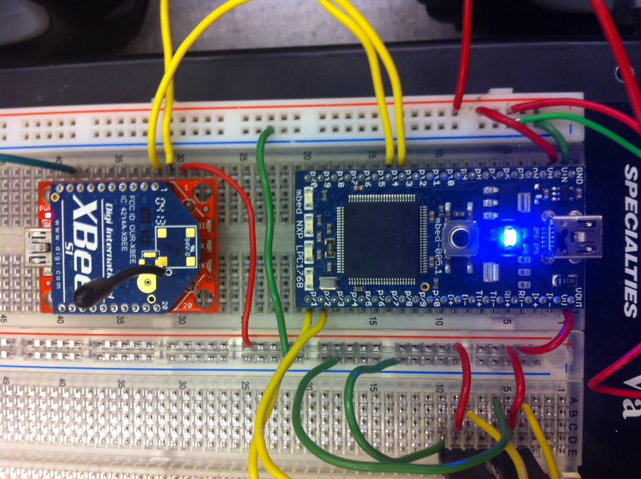
Connecting Xbee to Mbed
Mbed - - - Xbee Module
- p13- - - - - p3 (DIN)
- p14- - - - - p2 (DOUT)
- VOUT- - - p1 (VCC)
- GND- - - - p10 (GND)
Note: Xbee Modules had a wide range of breakout boards where some pins are switch and the VCC pin could be right next to the GND pin. Double check datasheets and pin outs to make sure there is not a misplaced connection. Also, it is recommended to have two USB connections to mbed for debugging purposes when you are trying to learn and understand how the modules work. Using the XCTU software from Digi is extremely helpful and recommended.
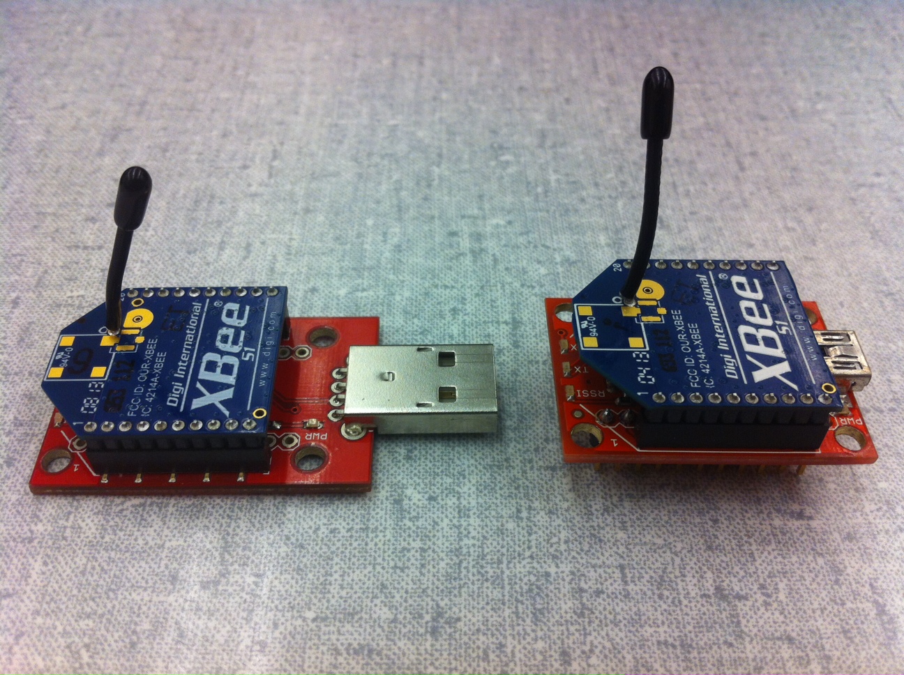
Connecting General Components like H-Bridge, Motors, and Battery
Since the readers implementation may not use the same H-Bridge or hardware components the demo will provide the specific implementation connections used and general use guidelines
General Use Guidelines
GND of Battery should be connected to the GND of mbed. VCC of Battery should also be connected to mbed on the Vin pin as long as the voltage is between 4.5v-14.0v. Additionally the VCC on the battery should be connected to the pins that give power to the motors located on the H-bridge. Double Check this is not the VCC for the H-bridge chip itself.
GND of the H-bridge should also be connected to the GND of mbed (and therefore battery GND also). Depending on the Voltage needed to power the H-bridge you can use mbed's Vout (3.3v) or VU (5v) pin. H-bridge will need mbed PwmOut pins to allow the H-bridge to drive the motors at different speed (and direction depending on the model of H-bridge), so connect some PwmOut mbed pins to the correct pins on the H-bridge. The demo code uses pins 22,21. Some boards also need Digital Out pins to control the motor direction, but the H-bridge use in this demo does not need these pins so add them as needed.
Specific Implementation Used in this Demo
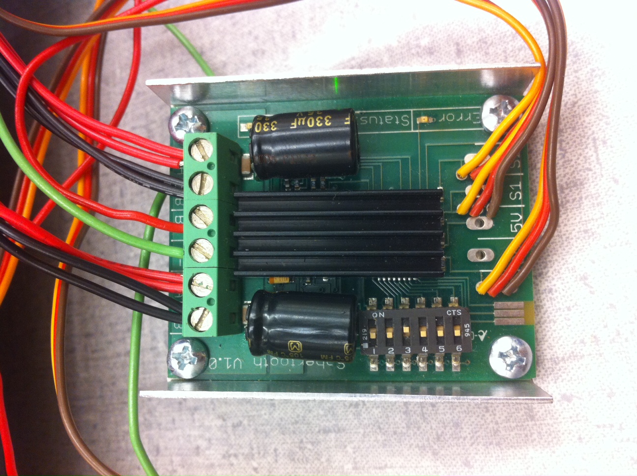
The H-bridge used for this implementation is the Sabertooth v1. Since there are 4 motors being used the motors were connected to this board in pairs. A pair of the positive ends of the motors went to M1A, and the other two connected to M2A. Two pairs of the ground ends that have their corresponding positive wire connected to M1A were connected to M1B and the last two were connected to M2B. Additionally the PwmOut pins used to control motor speed and direction were pins 21 and 22. These were connected to the S1 and S2 channels respectively (see data sheet). VOUT and GND on mbed were also connected to each channel to give the board power and ground. All these connections can be figured out by referring to the data sheet at: https://www.dimensionengineering.com/datasheets/Sabertooth2x10RC.pdf
There was a 6 cell 7.2v 1500mAh NiCD battery used to power all the parts that was connected exactly in the same manner as the general guidelines section.
H-Bridge (This demo used a Sabertooth v1; VCC is red, black and green are ground, the colorful 3 sets of 3 wires are from the Sabertooth H-Bridge see the data sheet to know what each color does):
Mbed and Xee Connections that were described above (all wiring is color coded: green is ground, red is VCC, yellow is serial data or PWM):
All connections shown between battery, mbed, and xbee:
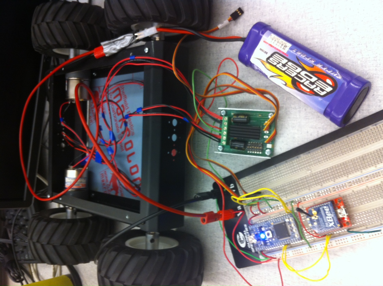
Drive ready setup for the robot:

Software to Run the Robot
Wireless Xbee Controlled from Computer Keyboard with Differential Drive
#include "mbed.h"

DigitalOut myled(LED1); //to notify when a character was received on mbed
Serial xbee(p13, p14); //used to connected the mbed to the xbee over Serial UART comm.
Serial pc(USBTX, USBRX); //used to connect to pc for debugging through a virtual COM port
PwmOut wheel1(p21); //signal for speed/direction to right wheels
PwmOut wheel2(p22); //singal for speed/direction to left wheels

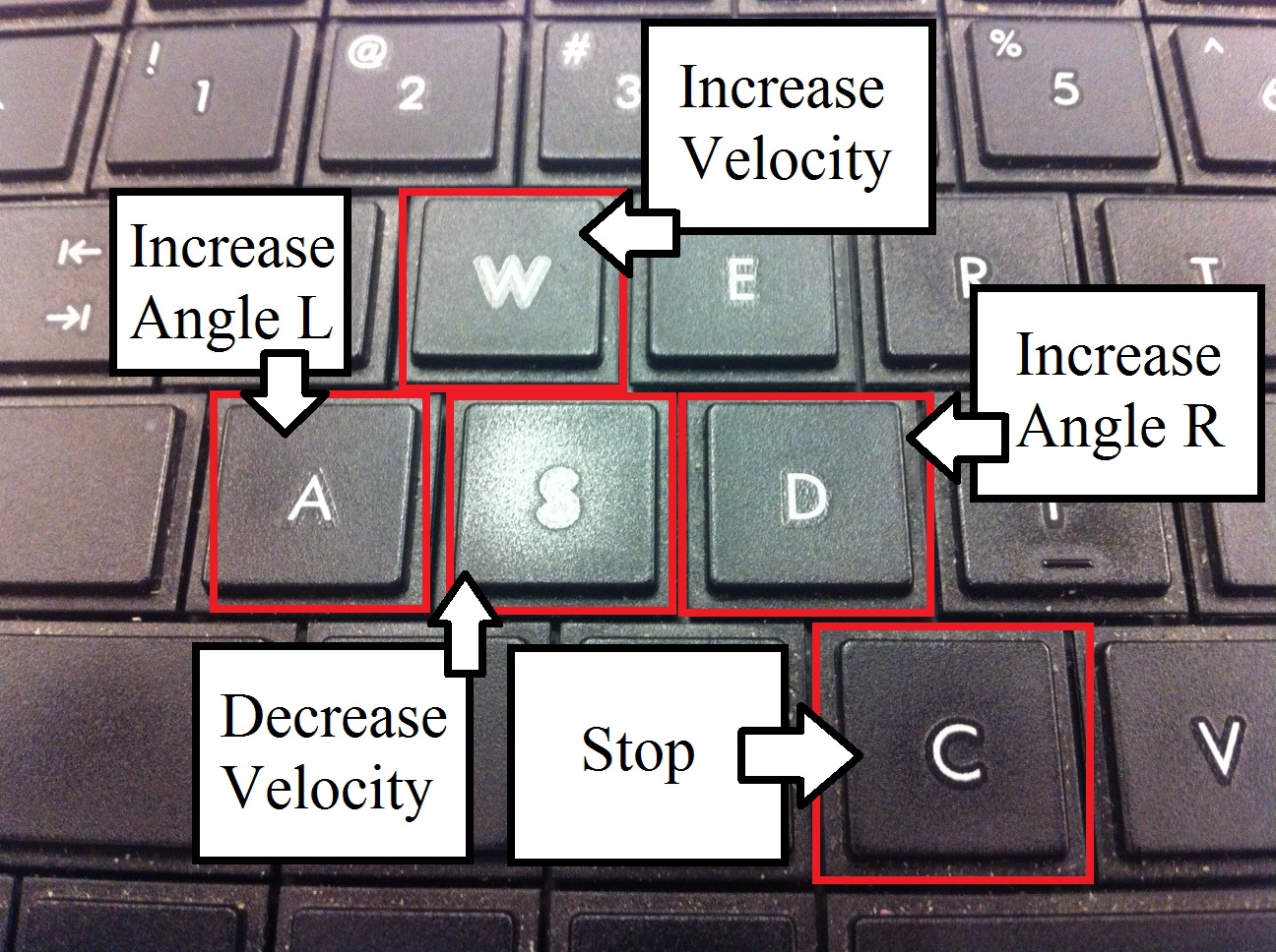
#define INCREASE 0x77 //w key
#define DECREASE 0x73 //s key
#define RIGHTER 0x64 //d key
#define LEFTER 0x61 //a key
#define CHILL 0x63 //c key
#define MAX_VEL 0.00012 //calculated maximum for spefic model robot maxw = R/2(Vr+Vl)
#define MIN_VEL 0.00006 //calculated minimum for spefic model robot minw = R/L(Vr-Vl)(use oppossite velocity maxes from the increase)
#define MAX_OME 0.0002 //calculated maximum for spefic model robot maxw = R/L(Vr-Vl)
#define MIN_OME -0.0002 //calculated minimum for spefic model robot minw = R/L(Vr-Vl)(use oppossite angle maxes from the right)
#define RADIUS 0.06 //measured radius of wheel in meters
#define LEN 0.3 //length of distance from middle of on wheel to the middle of an oppossite wheel

float velocity = 0.00009; //vl,vr == 0 when velocity is set to this speed with 0 angle(omega)
float omega = 0.0; //turning angle
float v1 = 0.0015, v2 = 0.0015; //Due to the type of Pwm input the Sabertooth v1 takes, this is the signal for the robot to not move
char current[32]; //holds the value of the character that was read

void eval_command(){ //this calkback function executes every time a Serial intterupt is generated to get the command sent
    myled = 1; //notification of character received
    switch(xbee.getc()){ //switch to tell the character that was pressed
        case INCREASE:
            velocity+=0.000005;
            if(velocity > MAX_VEL){ //to saturate the speed (upper lim.)
                velocity = MAX_VEL;
            }
            break;
        case DECREASE:
            velocity-=0.000005;
            if(velocity < MIN_VEL){ //to saturate the speed (lower lim.)
                velocity = MIN_VEL;
            }
            break;
        case RIGHTER:
            omega+=0.000025;
            if(omega > MAX_OME){ //to saturate the angel (rightward lim.)
                omega = MAX_OME;
            }
            break;
        case LEFTER:
            omega-=0.000025;
            if(omega < MIN_OME){ //to saturate the angel (leftward lim.)
                omega = MIN_OME;
            }
            break;
        case CHILL:
            omega = 0.0;  //in case robot goes out of control, this will stop it by pressing c key
            velocity = 0.00009;
    }
    myled = 0;
    v1 = ((2.0*velocity) + (omega*LEN))/(2*RADIUS); //calculates the seperate wheel velocities to go in the
    v2 = ((2.0*velocity) - (omega*LEN))/(2*RADIUS); //intended direction and speed
    //For Debugg to output to virtual COM port on mbed to test before robot is driven
    pc.printf("\rV = %1.6f, w = %1.6f, v1 = %1.6f, v2 = %1.6f",velocity,omega,v1,v2);
}

int main() {
    myled = 0;
    wheel1.period(0.20);
    wheel2.period(0.20);
    void (*fpointer)(void) = &eval_command;
    xbee.attach(fpointer,Serial::RxIrq); //attach a function to be done when a command is sent from the computer keyboard
    while(1) {
        wait(0.1);
        wheel1.pulsewidth(v1); //output the current speed value to right motor
        wheel2.pulsewidth(v2); //output the current speed value to left motor
    }
}
Keyboard Input Buttons:
Driving Robot Video:
1 comment on Wireless Xbee Controlled Robot from Windows 7 Computer Keyboard with Differential Drive:
Please log in to post comments.

Hello,
I am trying to use your code for my differential drive robot. I have the following questions for you 1. What DIP switch configuration did you use in sabertooth? 2. If we change the v1 value to 1 to maximum PwM signal, the motor does not run. Why?
I am a beginner in this area, and I would really appreciate any help.