W5UXH CW Keyer-Keyboard
Short summary:
This project is a migration of software and features from my ATmega328P CW keyer/keyboard. Rather than repeat the description of the features here, see this web page: https://sites.google.com/site/w5uxhatmega328pkeyerkbd/home
In a minimum configuration, the mbed can be used with only a piezo speaker and a NPN transistor keying circuit. In this configuration, the built in USB Mini B connector on the mbed board is used for program download, for the serial port console connection, and for DC power. A keyboard on a desktop or laptop computer is the "CW keyboard" and the display is in a window on the computer. I suggest using PuTTY as the terminal emulator. The basic keyboard features are provided in this configuration, but canned messages and probably some other items are not implemented using the terminal emulator due to the reduced flexibility of keyboard decoding. So I really suggest using the dedicated USB keyboard (see below).
In a stand alone configuration, the mbed needs a USB Type A Female connector wired to the mbed (to connect a USB keyboard) and a 4x20 LCD display. Optionally, the mbed USB port can still be used for a display console, or a dedicated serial port can be used with either a RS-232 converter or a serial to USB converter. Two 7805 regulators are used to provide power to the mbed, LCD, USB keyboard, and optional RS-232 converter. External 12VDC (nominal) is used to power the system. Total current requirement is approximately 200 ma, 100 ma for the MBED board and 100 ma (nominal) for the LCD. A USB host can also provide the power instead of using the 7805 regulators and external DC source.
I do not intend to try to sell any of the mbed keyers. This project would not be of interest to someone who just wants an "off the shelf" keyer/keyboard. One would need to have some interest in playing with the hardware and software. The mbed provides a really flexible platform for this.
This link should go to a short video that shows the "final package" in a few still frames followed by video showing the console window:
http://sdrv.ms/KD7QZH (This link shows the version that is seen in the photo below.)
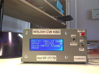
I have used the Cool Components breakout board in several prototypes: http://www.coolcomponents.co.uk/catalog/mbed-lpc1768-workshop-development-board-p-608.html. I have decided it definitely is not worth the cost for this project, and will use a simple perfboard layout in the future. Here is a photo of the front panel of the "final package":

"Format" of the following postings: After the first post of 10 April 2012 further down this page, I am posting brief updates in reverse chronological order so the most recent comments are here at the top.
Most recent ZIP file archive: /media/uploads/W5UXH/w5uxh-mbed-keyer-2012-10-11-testbuild.zip
(I rebuilt the project to verify that it is still working with recent compiler changes.)
17 Mar 2013: I have added support for using a PS-2 keyboard as well as the USB keyboard. The interrupt routine and scancode decoder is working. I have not handled special command keys yet, only the standard characters are being generated as CW, but it is just a matter of a bit more work to fully support the features available with the PS-2 keys. These will be the functions implemented in my AVR keyers. The decoding of USB and PS-2 differ such that some keys cannot be used for the same functions on the two sets of keys, but all functions found in the AVR keyers should be found in the MBED keyer (I think).
9 Mar 2013: The USB keyboard interface still glitches from some discharges, but it is definitely improved compared to the glitches when the isolator is not used. I am not sure how much difference there is when using a separate DC supply though.
I am now adding Hi-Per Mite filters to one of the packaged MBED keyers to allow using it with iCW (internet CW) and plan to start adding features that have been added to the AVR keyers in the past 6 or 8 months.
20 Feb 2013: I have not worked on this project since last July. I did order a USB Opto-Isolator to see if it cures the static discharge glitch and finally did a quick test today. It appears the isolator is doing the job. My recollection is that I did not find much information about USB opto-isolators (I suppose they are complicated by the bi-directional nature of the differential USB bus). The one I ordered came from this site: http://www.circuitsathome.com/measurements/usb-isolator. My understanding is that the DC supply required by the small assembly must be separate from the DC supply to the MBED in order to provide the necessary isolation. I have induced a number of strong discharges and so far none have glitched the USB interface for the keyboard, so this is very encouraging.
9 July 2012: I moved the final package to use with the rig and the Rosewill RK-9000 keyboard. I found that static discharges to my ground points that I always touch before operating the rig are glitching the keyboard USB interface, requiring a processor reset. This is not the case with the Cherry G81-3000LUNUS keys. I have installed 1K pullups on all three MBEds reset lines and 0.1 uF caps on one or more. These seem to prevent the processor from resetting but I had continued to notice the USB flash drive disconnecting, then reconnecting, in response to discharges. I need to look into doing a USB reset when the error message from the USB software is triggered: "ProcessDoneQueue status 81 5" to see if this reconnects the USB keys without requiring a manual reset of the program.
6 July 2012: Most of the remaining planned features have been implemented:
Non-volatile settings stored in local file system now include Curtis Emulation mode, RIG key and Sidetone ON/OFF states.
Current settings now written back to the settings.txt file with the shift-ScrollLock operation.
Message preview function added. Canned message abort when paddle closed.
27 June 2012: Support for the paddle added, more details later, working well.
29 May 2012:
I have refined a number of minor things, particularly related to the effect of the backspace key on the console and LCD displays. The backspace key from both console kbd and USB kbd now has no effect on the displays if there are no characters still in the transmit buffer. There are several other minor improvements but I would have to stop and think about what they might be, so who knows.
I continue to use UART1 as the primary console. I prefer to not leave the mbed USB cable connected except when doing development. When I hibernate the desktop at night, if the cable is still connected, then the mbed remains powered on even though I have "turned off" the keyer. This should not be a problem at all, but I prefer to completely power down.
Currently the USB-A connector used for the USB keys is powered from the external DC source on the Cool Components breakout board. I have ordered some Schottky diodes (low voltage drop) and plan to "wire OR" the external DC with the mbed USB DC output (pin 39) so the keyer should work when powered only from USB. I believe this will work, but I will see when the diodes arrive.
In the current prototype I use two different interfaces for UART1 to the console. One is a RS-232 converter. The other is a USB converter. The RS-232 converter requires an external serial to USB converter. The USB converter does not, it connects directly to a USB cable from the desktop. I use a DPDT switch to select between the two. The USB converter is convenient since it does not require the external converter cable. But the internal USB converter somehow causes problems with the mbed if a USB cable is not connected. This relates to a problem I have not figured out yet. If I have a unterminated cable connected to the mbed UART1 RX and TX pins (6" long) the mbed does not start up. If the cable is connected to the USB converter but no USB cable is connected so the USB converter is not powered on, the same problem occurs. The RS-232 converter is powered from the internal power and the mbed boots up fine in this condition. So I leave the toggle switch selecting the RS-232 converter if the USB converter is not powered. I realize this is not going to be clear to anyone else, but hopefully in the future I will have some idea what I am describing when I am trying to relearn the details of this project after forgetting everything I knew.
23 May 2012:
The program is now reasonably fleshed out and stable. Speed control from the arrow keys on both the USB keyboard and the console keyboard is implemented. The buffer status is displayed on both the LCD and the console. A #define is used to determine if the console is the USB (UART0) serial port or the RS-232 (UART1) serial port and my current option is the RS-232 port. I implemented a Fifo class in queues.cpp and queues.h for the four buffers. I have not tried to use it with the rig for normal operation but believe it might be robust and functional enough for this. I have implemented the call ID detection and automatic timer reset. I now use the local file system to store files, one for the initial settings of speed etc. to be used at power on. A set of nine more files are used for the canned messages on the keypad numeric keys 1-9. Note that the canned messages are only implemented for the dedicated USB set of keys, not for the console keyboard.
The primary goals for the software apply to use of the dedicated USB keys. I will include as much duplication as possible for the console keyboard, but I am not able to decode the console keyboard in the same way that I am able to decode the dedicated USB keys. This prevents me from using the keypad numeric keys for the canned messages. So there will be a number of features that will not be available on the console, or will need to be implemented differently.
There is still a lot of work to do and I have not begun to work on implementing support for the paddle.
The following video shows the console activity while sending CW. The text will be a bit easier to read if the "watch on Youtube" button is used. The automatic reset of the 10 minute timer can be seen in the first few seconds when I identify by sending W5UXH. The buffer status can be seen in the upper right corner. The terminal emulator used is PuTTY. The second video shows the mbed mounted in an enclosure for testing.
25 Apr 2012:
I worked on processing the raw data packets delivered by AutoEventCallback (from USBHostShell) and after a brief test, the USB keys now seem to be working properly. I would expect some subtle problems could remain. I do not have auto repeat for any keys and am not sure if I will bother with that. The project is still very preliminary but basically functional. Speed control is still only from the console port, not from the USB keys. I will not upload another zip file for the project until I have at least basic speed control from the USB keys.
24 Apr 2012:
I believe I see my way over the brick wall. Briefly:
I think I have a better understanding now. I am pretty sure the behavior I am seeing is normal. My previous experience with decoding USB keys was at a relatively low level (the "event" level in Linux, where events reported key presses and key releases etc.). I believe the data packets I am dealing with in USBHostShell are at a "lower level" and I need to process the packets to keep track of key presses and releases. I think I will be able to deal with this successfully.
23 Apr 2012:
I have hit a brick wall on the USB keyboard handler. Yesterday I had a "major breakthrough" when I got USBHostShell working with the keyer so I could read key codes from the USB data packet, convert to ASCII and stick in the cw generator queue. I quickly edited a few of the USB key codes into my lookup table (from the PS-2 project) and thought it was working well. I then filled out the lookup table and tried normal typing and immediately started hearing "extra" cw characters. I would really like to use USB keys instead of PS-2 but I do not know if I will ever be able to dif into the black box of USB to be able to program the host controller from scratch or to learn enough about C++ to be able to disect the USBHostShell code.
--------------------
10 April 2012:
I am working on migrating my AVR ATmega328P project to the mbed LPC1768. The AVR project uses PS-2 keys. I hope I will be able to figure out the USB Host mode on the mbed for use with a USB keyboard.
As of 10 April 2012, I have a very preliminary version working with the Serial pc feature used as the input. I ordered a "breakout board" from Cool Components to allow hooking up a set of USB keys. My goal is to be able to identify every individual key on the keyboard at the "event level" so I can assign functions to the same keys I use on the PS-2 project and in another project using the Mini2440 Embedded Linux board. I used the Mini2440 as a front end on the AVR keyer so I could use USB keys. But the mbed will be a much better fit if I can get the USB keys working the way I want.
Documentation for the AVR project is here: https://sites.google.com/site/w5uxhatmega328pkeyerkbd/home. I have not documented the Mini2440 project, but a video is here: http://www.youtube.com/watch?v=XNQCLlffFTE
I am new to C++ and have avoided it for many years. The mbed environment has been great for allowing me to import needed features without the need to understand much about OOP. The online compiler works well, but I must admit I would love to have an offline environment that provides the mbed library. I have used EMACS as my editor for 20 years or more and will continue to use it here, with the complication of trying to keep my local source in sync with the online environment.
21 April 2012:
The Cool Components order was shipped on 5 April 2012 using the cheapest shipping method (air mail, no insurance or tracking) and still has not arrived, so I ordered some USB connectors from Mouser and have connected one to one of my breadboards. The Cool Components board looks like it will be very useful so I hope it eventually arrives.
I think there is some chance that by working with BlueUSB I might start to learn a bit about C++, which would be a good thing. (I have been experimenting with BlueUSB the past few days.)
I doubt there are many CW operators who would ever show up here and be interested, but I will still try to document this project to some extent. I have a very preliminary implementation that works well using the Serial input stream (UART0) from a terminal emulator. A crude windowing display is controlled with ANSI escape sequences to allow displaying the current speed in the top section of the terminal emulator window, with the transmitted characters in the lower section. Speed is controlled UP/DOWN with the four arrow keys in steps of 1 or 5 WPM.
When using a CW keyboard in a qso, I typically run 60 to 65 wpm and the mbed is performing well, with precise timing, at these speeds. I still need to get an external USB keyboard working. I have experimented with BlueUSB and been able to use it to identify the key code for each key, but I need to learn enough about USB and C++ to be able to integrate the appropriate functions from BlueUSB into the keyer. If I am able to do that, then I will probably also add a PS-2 interface so that the keyer can be operated from a terminal emulator, from USB keys, from PS-2 keys and from a paddle.
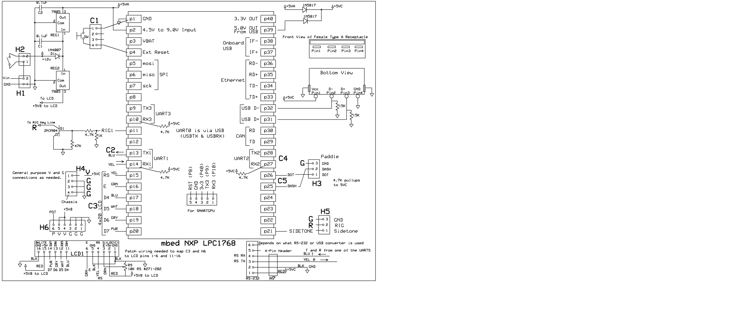
The following sketch is a crude schematic of my breadboard for the keyer:

This should only be used as a general guide. It is subject to having errors or omissions because I have gone through various iterations as the project progressed. Schottky diodes are used to functionally "OR" the DC from the 7805 with the USB-5VDC from the mbed so that the USB keys, RS-232 converter, and pull up resistors for things like the paddle input all have power when the keyer is connected to either USB or external DC alone. The LCD only operates from the external DC.
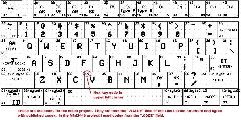
The next figure shows the HEX scan code for each key on the main section of the USB keyboard, as identified with a modified BlueUSB program that only displays output when a key is presses, in this format:
data 8: 02 00 04 00 00 00 00 00. (This was when Shift-A was pressed.)
The left hand most byte (I refer to it as byte0 in the figure) is the modifier byte. The next byte is the "OEM" reserved byte. The next byte is the first key code. If multiple keys are pressed, up to 6 key codes will be found. The modifier byte is the logic OR of all modifier keys that are pressed (CTRL, SHIFT, etc.).

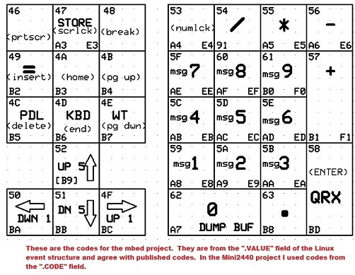
The next figure shows the keypad section:

I used an earlier drawing that had a different set of codes used in a previous Linux project and it is possible I have missed updating one or more keys. I realized this morning I had missed the SPACE key update to the new code and fixed it before uploading the figures.
The codes in the lower left corner are custom codes I use for special functions when I do the key code to ASCII conversion in the keyer program.
Please log in to post comments.
