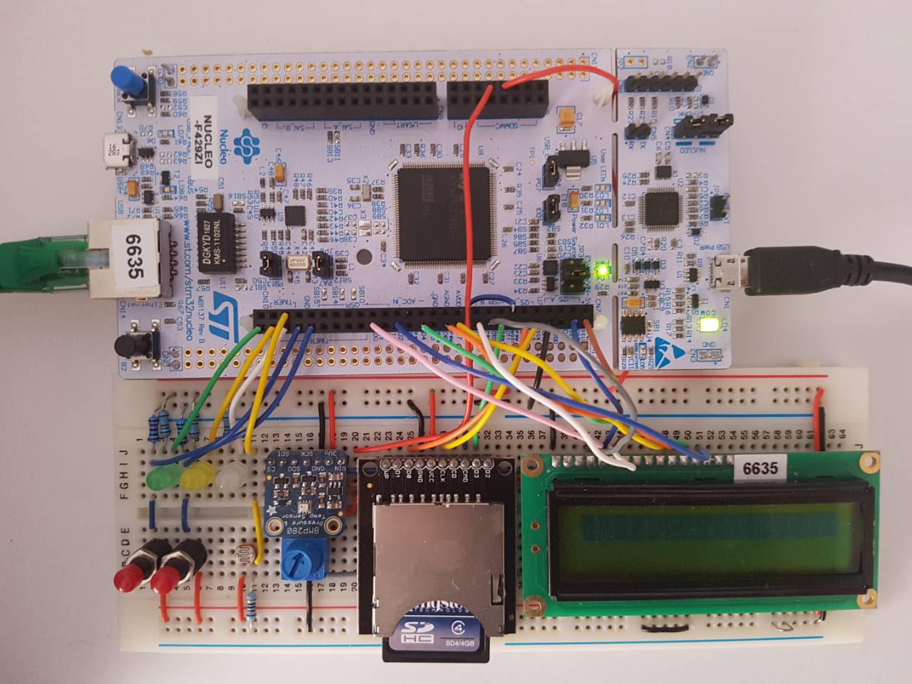
Contains necessary classes and functions for ELEC351

samplingMaster/samplingMaster.cpp
- Committer:
- Luka_Danilovic
- Date:
- 2018-01-09
- Revision:
- 7:92b4783af1d2
- Parent:
- 2:e2b885367ba8
File content as of revision 7:92b4783af1d2:
#include "mbed.h"
#include "samplingMaster.hpp"

/* Spec said that we are not allowed to use any third party code unless it is
from ARM or STmicroelectronics, so I wrote my own driver for sampling BMP280 &
ADC in succesion. Ths code for MPB280 was inspired by the BMP280 Datasheet:
[https://cdn-shop.adafruit.com/datasheets/BST-BMP280-DS001-11.pdf]
and BMP280 mbed library by "charlie":
[https://os.mbed.com/users/CHARLY/code/BMP280/] */

C_sensorData::C_sensorData()
{

    //********************************LDR ADC*********************************//
    AnalogIn ldrADC(PA_0);      // Establish Analog In for ADC

    //******************************BMP280 I2C********************************//
    I2C sensorLink(D14, D15);   // Establish I2C comms

    inst[0] = CONTROL_REGISTER; // Register address
    inst[1] = 0b01101101;       // Temp x4, Pressure x4, Forced mode
    sensorLink.write(I2C_adr, inst, 2);

    inst[0] = Tsb_IIR_REGISTER; // Register address
    inst[1] = 0x00;             // No standby, No IIR filter
    sensorLink.write(I2C_adr, inst, 2);

    inst[0] = DIG_Tn_REGISTERS; // Read trimming parameters instruction
    sensorLink.write(I2C_adr, inst, 1);
    sensorLink.read(I2C_adr, inst, 6);

    /* For instructions how to decode trimming parameters please refer to the
    BMP280 datasheet, page 21, chapter 3.11.2, table 17: "Compensation parameter
    storage, naming and data type" */
    T1Trim = (inst[1]<<8)|inst[0];
    T2Trim = (inst[3]<<8)|inst[2];
    T3Trim = (inst[5]<<8)|inst[4];

    inst[0] = DIG_Pn_REGISTERS; // Read trimming parameters instruction
    sensorLink.write(I2C_adr, inst, 1);
    sensorLink.read(I2C_adr, inst, 18);

    /* For instructions how to decode trimming parameters please refer to the
    BMP280 datasheet, page 21, chapter 3.11.2, table 17: "Compensation parameter
    storage, naming and data type" */
    P1Trim = (inst[ 1]<<8)|inst[ 0];
    P2Trim = (inst[ 3]<<8)|inst[ 2];
    P3Trim = (inst[ 5]<<8)|inst[ 4];
    P4Trim = (inst[ 7]<<8)|inst[ 6];
    P5Trim = (inst[ 9]<<8)|inst[ 8];
    P6Trim = (inst[11]<<8)|inst[10];
    P7Trim = (inst[13]<<8)|inst[12];
    P8Trim = (inst[15]<<8)|inst[14];
    P9Trim = (inst[17]<<8)|inst[16];
}

TDS_sensorData C_sensorData::read()
{
    //*********************************SETUP**********************************//
    TDS_sensorData sensorData;  // Type def struct to hold the data
    AnalogIn ldrADC(PA_0);      // Establish Analog In for ADC
    I2C sensorLink(D14, D15);   // Establish I2C comms

    /* N.B in forced mode you must write to CONTROL_REGISTER to wake the IMU up.
    It automaticly sleeps when measurments are aquired but leaves the registers
    readable for the I2C link                                                 */
    inst[0] = CONTROL_REGISTER; // Register address
    inst[1] = 0b01101101;       // Temp x4, Pressure x4, Forced mode
    sensorLink.write(I2C_adr, inst, 2);

    //******************************TEMPERATURE*******************************//
    inst[0] = TEMP_ADDRESS_VAL; // Start of temperature register
    sensorLink.write(I2C_adr, inst, 1);
    sensorLink.read(I2C_adr, &inst[1], 3);

    tempT = (inst[1]<<12)|(inst[2]<<4)|(inst[3]>>4);
    //             ^             ^            ^
    //      MSB REGISTER  LSB REGISTER  X_LSB REGISTER

    /* For instructions how to compensate values please refer to the
    BMP280 datasheet, page 21 & 22, chapter 3.11.3, pseudo code */
    tempA = ((((tempT>>3)-(T1Trim<<1)))*T2Trim)>>11;
    tempB = (((((tempT>>4)-T1Trim)*((tempT>>4)-T1Trim))>>12)*T3Trim)>>14;
    tempT = tempA+tempB;
    sensorData.temp = ((float)((tempT * 5 + 128) >> 8))/100;

    //********************************PRESURE********************************//
    inst[0] = PRES_ADDRESS_VAL; // Start of presure register
    sensorLink.write(I2C_adr, inst, 1);
    sensorLink.read(I2C_adr, &inst[1], 3);

    tempP = (inst[1]<<12)|(inst[2]<<4)|(inst[3]>>4);
    //             ^             ^            ^
    //      MSB REGISTER  LSB REGISTER  X_LSB REGISTER

    /* For instructions how to compensate values please refer to the
    BMP280 datasheet, page 21 & 22, chapter 3.11.3, pseudo code.

    Please note that the compensation in the datasheet is done with 64 bit
    signed values. However, "charlie's" BMP280 driver which does the
    compensation using 32 bit signed values has inspired me to write my
    compensation algorithm as follows. This makes the algorithm more efficient
    without sacrifising relevant acuracy

    N.B the pressure calculated by the following algorithm is in hPa which is
    a newer unit with equivalence of: 1hPA = 1mbar*/

    tempA = (tempT>>1)-64000;
    tempB = (((tempA>>2)*(tempA>>2))>>11)*P6Trim;
    tempB = tempB+((tempA*P5Trim)<<1);
    tempB = (tempB>>2)+(P4Trim<<16);
    tempA = (((P3Trim*(((tempA>>2)*(tempA>>2))>>13))>>3)+((P2Trim*tempA)>>1))>>18;
    tempA = ((32768+tempA)*P1Trim)>>15;

    if(tempA == 0) {
        sensorData.pres = 0;
    }
    tempP = (((1048576-tempP)-(tempB>>12)))*3125; // Compensate for 64 bit loss
    if(tempP < PREAS_UPER_LIMIT) {
        tempP = (tempP<<1)/tempA;
    } else {
        tempP = (tempP/tempA)*2;
    }

    tempA = ((int32_t)P9Trim*((int32_t)(((tempP>>3)*(tempP>>3))>>13)))>>12;
    tempB = (((int32_t)(tempP>>2))*(int32_t)P8Trim)>>13;
    sensorData.pres = ((float)((tempP+((tempA + tempB+P7Trim)>>4))))/100;


    //******************************LIGHT LEVEL*******************************//
    sensorData.ligt = ldrADC.read();            // Read ldr value

    //RETURN SENSOR DATA//
    return sensorData;
}