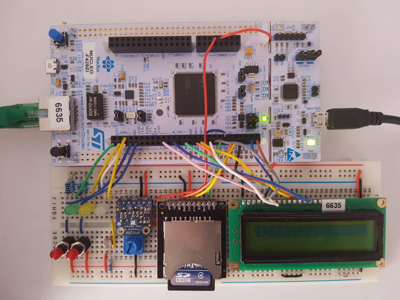
Contains necessary classes and functions for ELEC351

Diff: samplingMaster/samplingMaster.cpp
- Revision:
- 2:e2b885367ba8
--- /dev/null	Thu Jan 01 00:00:00 1970 +0000
+++ b/samplingMaster/samplingMaster.cpp	Wed Dec 27 15:28:20 2017 +0000
@@ -0,0 +1,135 @@
+#include "mbed.h"
+#include "samplingMaster.hpp"
+
+/* Spec said that we are not allowed to use any third party code unless it is
+from ARM or STmicroelectronics, so I wrote my own driver for sampling BMP280 &
+ADC in succesion. Ths code for MPB280 was inspired by the BMP280 Datasheet:
+[https://cdn-shop.adafruit.com/datasheets/BST-BMP280-DS001-11.pdf]
+and BMP280 mbed library by "charlie":
+[https://os.mbed.com/users/CHARLY/code/BMP280/] */
+
+C_sensorData::C_sensorData()
+{
+
+    //********************************LDR ADC*********************************//
+    AnalogIn ldrADC(PA_0);      // Establish Analog In for ADC
+
+    //******************************BMP280 I2C********************************//
+    I2C sensorLink(D14, D15);   // Establish I2C comms
+
+    inst[0] = CONTROL_REGISTER; // Register address
+    inst[1] = 0b01101101;       // Temp x4, Pressure x4, Forced mode
+    sensorLink.write(I2C_adr, inst, 2);
+
+    inst[0] = Tsb_IIR_REGISTER; // Register address
+    inst[1] = 0x00;             // No standby, No IIR filter
+    sensorLink.write(I2C_adr, inst, 2);
+
+    inst[0] = DIG_Tn_REGISTERS; // Read trimming parameters instruction
+    sensorLink.write(I2C_adr, inst, 1);
+    sensorLink.read(I2C_adr, inst, 6);
+
+    /* For instructions how to decode trimming parameters please refer to the
+    BMP280 datasheet, page 21, chapter 3.11.2, table 17: "Compensation parameter
+    storage, naming and data type" */
+    T1Trim = (inst[1]<<8)|inst[0];
+    T2Trim = (inst[3]<<8)|inst[2];
+    T3Trim = (inst[5]<<8)|inst[4];
+
+    inst[0] = DIG_Pn_REGISTERS; // Read trimming parameters instruction
+    sensorLink.write(I2C_adr, inst, 1);
+    sensorLink.read(I2C_adr, inst, 18);
+
+    /* For instructions how to decode trimming parameters please refer to the
+    BMP280 datasheet, page 21, chapter 3.11.2, table 17: "Compensation parameter
+    storage, naming and data type" */
+    P1Trim = (inst[ 1]<<8)|inst[ 0];
+    P2Trim = (inst[ 3]<<8)|inst[ 2];
+    P3Trim = (inst[ 5]<<8)|inst[ 4];
+    P4Trim = (inst[ 7]<<8)|inst[ 6];
+    P5Trim = (inst[ 9]<<8)|inst[ 8];
+    P6Trim = (inst[11]<<8)|inst[10];
+    P7Trim = (inst[13]<<8)|inst[12];
+    P8Trim = (inst[15]<<8)|inst[14];
+    P9Trim = (inst[17]<<8)|inst[16];
+}
+
+TDS_sensorData C_sensorData::read()
+{
+    //*********************************SETUP**********************************//
+    TDS_sensorData sensorData;  // Type def struct to hold the data
+    AnalogIn ldrADC(PA_0);      // Establish Analog In for ADC
+    I2C sensorLink(D14, D15);   // Establish I2C comms
+
+    /* N.B in forced mode you must write to CONTROL_REGISTER to wake the IMU up.
+    It automaticly sleeps when measurments are aquired but leaves the registers
+    readable for the I2C link                                                 */
+    inst[0] = CONTROL_REGISTER; // Register address
+    inst[1] = 0b01101101;       // Temp x4, Pressure x4, Forced mode
+    sensorLink.write(I2C_adr, inst, 2);
+
+    //******************************TEMPERATURE*******************************//
+    inst[0] = TEMP_ADDRESS_VAL; // Start of temperature register
+    sensorLink.write(I2C_adr, inst, 1);
+    sensorLink.read(I2C_adr, &inst[1], 3);
+
+    tempT = (inst[1]<<12)|(inst[2]<<4)|(inst[3]>>4);
+    //             ^             ^            ^
+    //      MSB REGISTER  LSB REGISTER  X_LSB REGISTER
+
+    /* For instructions how to compensate values please refer to the
+    BMP280 datasheet, page 21 & 22, chapter 3.11.3, pseudo code */
+    tempA = ((((tempT>>3)-(T1Trim<<1)))*T2Trim)>>11;
+    tempB = (((((tempT>>4)-T1Trim)*((tempT>>4)-T1Trim))>>12)*T3Trim)>>14;
+    tempT = tempA+tempB;
+    sensorData.temp = ((float)((tempT * 5 + 128) >> 8))/100;
+
+    //********************************PRESURE********************************//
+    inst[0] = PRES_ADDRESS_VAL; // Start of presure register
+    sensorLink.write(I2C_adr, inst, 1);
+    sensorLink.read(I2C_adr, &inst[1], 3);
+
+    tempP = (inst[1]<<12)|(inst[2]<<4)|(inst[3]>>4);
+    //             ^             ^            ^
+    //      MSB REGISTER  LSB REGISTER  X_LSB REGISTER
+
+    /* For instructions how to compensate values please refer to the
+    BMP280 datasheet, page 21 & 22, chapter 3.11.3, pseudo code.
+
+    Please note that the compensation in the datasheet is done with 64 bit
+    signed values. However, "charlie's" BMP280 driver which does the
+    compensation using 32 bit signed values has inspired me to write my
+    compensation algorithm as follows. This makes the algorithm more efficient
+    without sacrifising relevant acuracy
+
+    N.B the pressure calculated by the following algorithm is in hPa which is
+    a newer unit with equivalence of: 1hPA = 1mbar*/
+
+    tempA = (tempT>>1)-64000;
+    tempB = (((tempA>>2)*(tempA>>2))>>11)*P6Trim;
+    tempB = tempB+((tempA*P5Trim)<<1);
+    tempB = (tempB>>2)+(P4Trim<<16);
+    tempA = (((P3Trim*(((tempA>>2)*(tempA>>2))>>13))>>3)+((P2Trim*tempA)>>1))>>18;
+    tempA = ((32768+tempA)*P1Trim)>>15;
+
+    if(tempA == 0) {
+        sensorData.pres = 0;
+    }
+    tempP = (((1048576-tempP)-(tempB>>12)))*3125; // Compensate for 64 bit loss
+    if(tempP < PREAS_UPER_LIMIT) {
+        tempP = (tempP<<1)/tempA;
+    } else {
+        tempP = (tempP/tempA)*2;
+    }
+
+    tempA = ((int32_t)P9Trim*((int32_t)(((tempP>>3)*(tempP>>3))>>13)))>>12;
+    tempB = (((int32_t)(tempP>>2))*(int32_t)P8Trim)>>13;
+    sensorData.pres = ((float)((tempP+((tempA + tempB+P7Trim)>>4))))/100;
+
+
+    //******************************LIGHT LEVEL*******************************//
+    sensorData.ligt = ldrADC.read();            // Read ldr value
+
+    //RETURN SENSOR DATA//
+    return sensorData;
+}
\ No newline at end of file