Car Automation
This year i have been set the task to design and build an automated car for my final year dissertation.
i am aware that there is another doing this project and i have viewed his page and decided its a good idea to up date this page, then use it to write the final 10k word report that has to go with it.
New parts added at the bottom of page
Parts Used:
- Standard RC Car Kit - 2 x Servos, Manual Speed control, DC motor, Main body
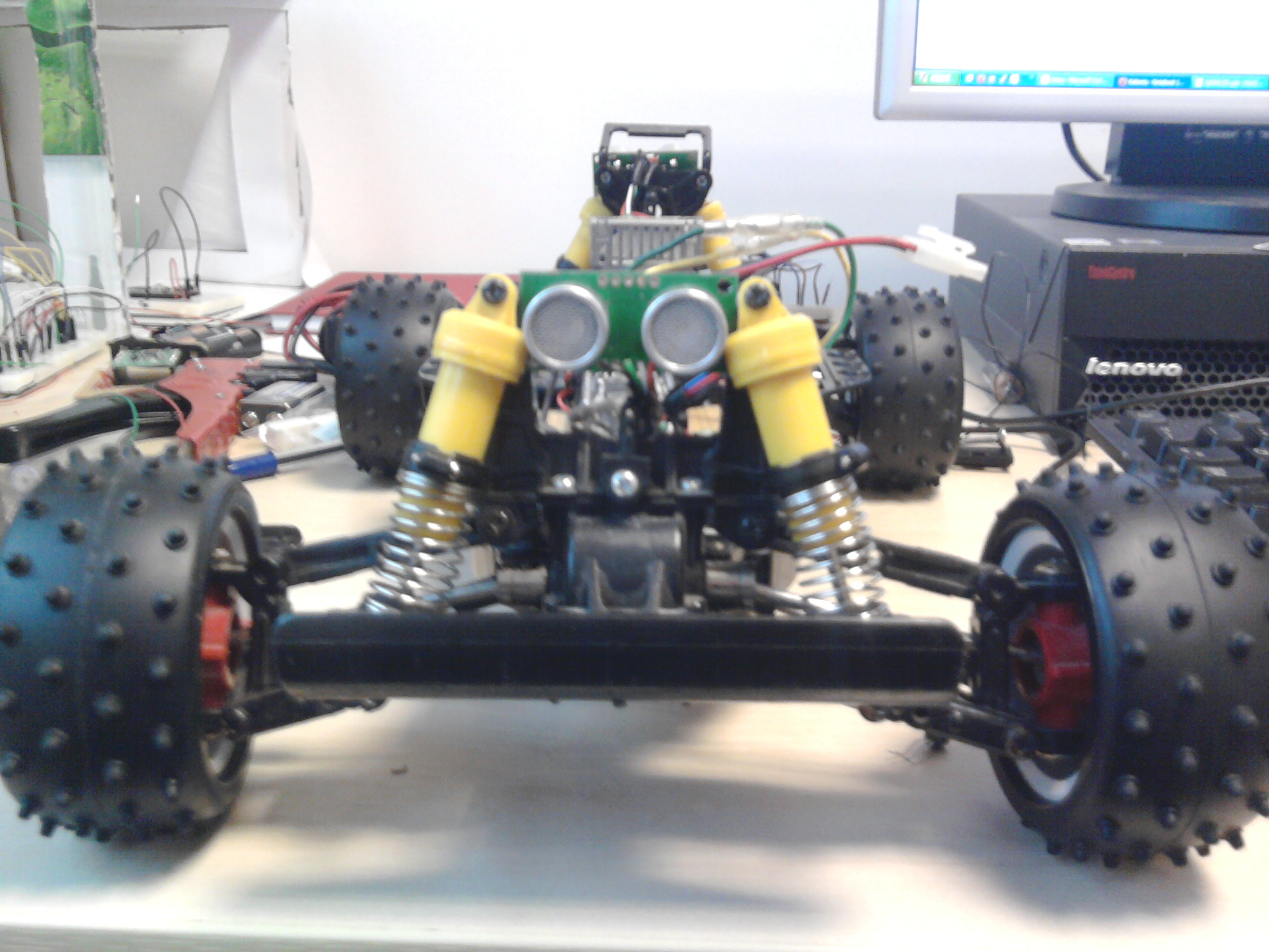
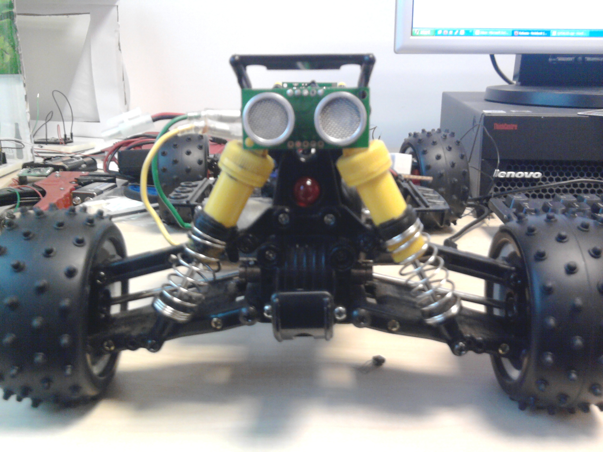
- 2x SRF05 Sensors
- Mbed
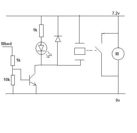
- DC motor Break - Relay, transistor and resistors
The story so far:
- Servo control For Forward and reverse:-
i am using an 3 stage analoge style speed control that came with the RC car, as the name suggests it has 3 speed stages fast, faster and too fast, i have thought about stepping it down but looks more work than it should be.
- Servo control for stearing
Stering works fine and wrote a bit of code to siplyfi the turning prosess:
void left (void) {
    turn.write(1);
}
void right (void) {
    turn.write(0);
}
just have to call left(); or right();, there is a bit of a whine from the servo but im sure this wont matter as it did it before with the remote reciver still attached.
- Ultrasonic sensor Front and Rear
the sensors (SRF05's - the only thing thats lying around Mbed's Lab) and the code i have implemented, does detect if an object in front and behind and are able to detect as close as 5cm, but it is only front and rear and is unable to accuratly judge the space beteen objects for the car to safly pass through.
- DC motor break to slow the car quicker
this was add as even with the detection sensors it would just cut the poer to the motor, then it just free wheels till it either stops in time or hits somthing, the dc moto shorts the motor saftly to allow a much faster stopping time.
- Steering
the car will look in front till it finds somthing in its path, if there is enough room to continue forward and turn (distance fount after lots of trial and error) it will other wise it will check the same for behind, with this im assuming that there will always be space to atlest start to reverse due to it comming from that direction.
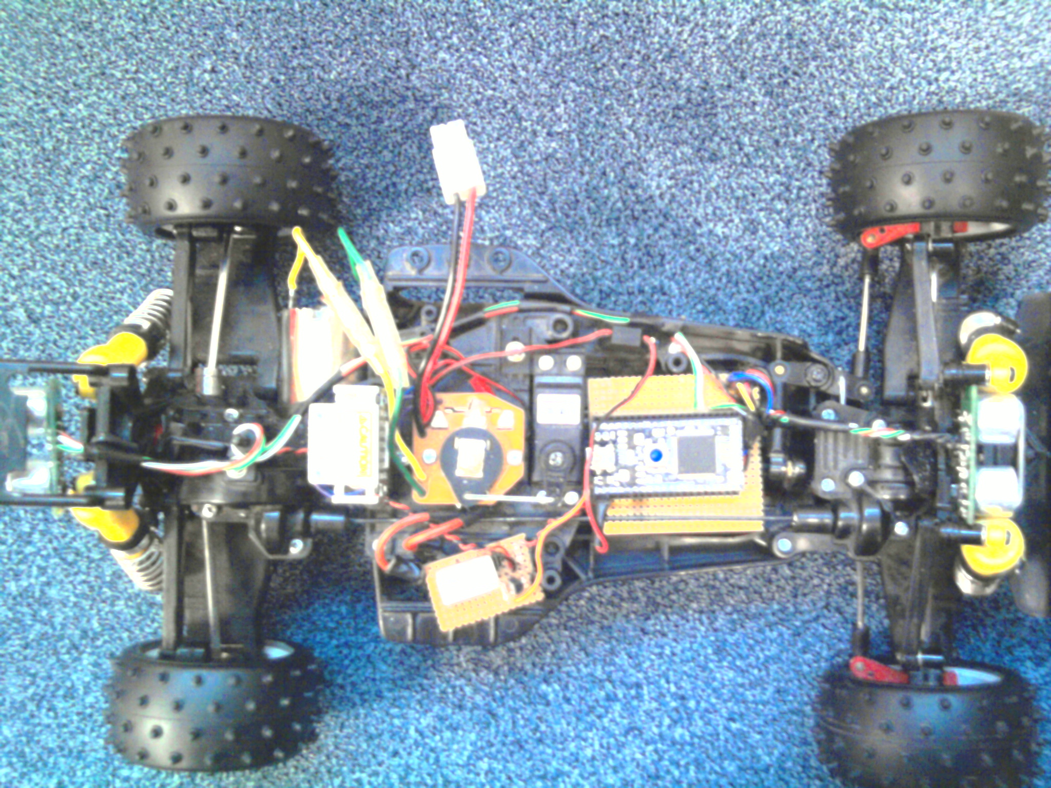
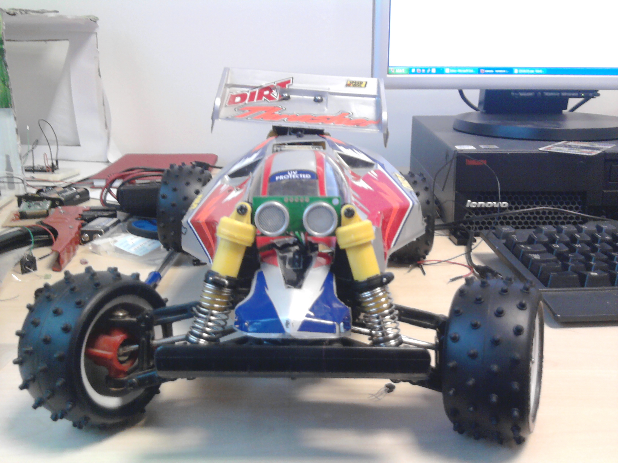
Photos:
Distance and Speed Sensor:
using a QRD1114 uv diode and photo transistor combi, i have been able to detect when a point (marked out by refelctive tape) on the wheel.
by using the time it takes for 1 full rotation of the wheel i can calculate distance travelled in a set time and from that i can calculate the speed and distace.
for this im using the inturpt and timer function to execute the function every time the pin has a rising edge (this means if its stopped then the sensor is still active the function wont be stuck in its self)
the timer will count the diffrence between 2 rising edges and calculate the speed, also with each rising edge the total rotations travelled will go up by 1 this is then multiplied by the circumference of the wheel.
Problems: no detection for loss of traction :- this is in the human element of driving
ESC - Electronic speed control
Speed & Distance Sensor
- QRD1114 - UV led + photo trasistor combo
- 1k resistor
General Description "The QRD1114 reflective sensor consists of an infrared emitting diode and an NPN silicon photodarlington mounted side by side in a black plastic housing. The on-axis radiation of the emitter and the on-axis response of the detector are both perpendicular to the face of the QRD1114. The photodarlington responds to radiation emitted from the diode only when a reflective object or surface is in the field of view of the detector."
i want the sensor to mesure the time between each pulse and add the total distance travelled,
to do this i am using the IntruptIn and the timer function, when the senstor detects a high pulse it will activate the intrupt function below:
int count,begin,end;
int single_spin;
const int wheel = 257 //in mm
int = Tdist=0;

void trigger()
{
end = timer.read_us();
count = count + 1; // accumulate distance
begin = timer.read_us();

single_spin = end - begin; //time for 1 spin in us
Tdist = wheel * count; //o/p in mm for now

}


int main() {
timer.start();
w.rise(&trigger);

    while(1) {
//Main Program here

    }
}
or something close to it, the output will be in mm but i will be scaling that to a real car tire at get a scale distance, Also this will give the speed of the car for each spin, it might be an idea to do som digital filtering and grab an averadge to get an aprox speed.
this will all eventualy be displayed on a screen on the car as well as being recorded to either an SD card or on board memory
test prog v1.0 car_wheel_sens
i have updated the speed sensor to use on board data logging, it shows how many turns the wheel has made and time it took for that 1 complete turn. it is all outputted to a .csv file where i can calculate the the speed and the total distance travelled.
#include "mbed.h"
#include "Servo.h"


DigitalOut myled(LED1);
DigitalOut myled2(LED2);
InterruptIn w(p16);
Timer timer;
LocalFileSystem local("local");
Servo serv (p21);

int count,begin,end;
int single_spin;
const int wheel = 257; //in mm
int Tdist=0;
int i =0;

void trigger() {
    FILE *fp = fopen("/local/out.csv", "a");

    count = count + 1;
    begin = timer.read_ms();
    single_spin = begin - end;
    myled2 = !myled2;
    fprintf(fp, "%d, %d\n", count, single_spin);
    end = timer.read_ms();
    fclose(fp);

}


int main() {
    timer.start();
    w.rise(&trigger);

    while (count < 5 ) // set this so it dont keep smashing in to walls !
     {

        serv.write(0.3);
        myled = !myled;
        wait(0.1);
    }

    serv.write(0.5);


}
V1.1 car_wheel_sens
having the write to file in the trigger i know is bad but i need it to record the data for each turn. if do not it would only then point to another function (which I may end up doing) but the problem with that if i get more that 1 trigger pulse it will compromise the data saved.
Currently working on:
the next parts to implement will be:
- servo mounted sensors - going for 2 extra side sensors
- Accelaromitor data logging
- compass direction control - will add if i have time
- advanced motor control - using electronic speed control unit
- side/width proximity sensors
- accurate speed and distance mesument (done - ish)
theres quite a bit there to work on i have more to do but i will add them as i come across them.
NB: full scaled speed is 71mph or actual speed is 7.1Mph or 3.2mps --- this was first test may be innacurate!
Problems:
- range sensors now no longer being read - i have recently been forced to use a mbed v2.1 (old v2.2 had "device not recognised") with red LED's but still a 2368 chip the range sensors are flashing as if they are recording but when the data should be read the car does not react i am using the same vision of the program .... the only things that are different are the ESC and the way it is powered. --- could be a power issue also possible that one has died and messing with the program/power shorting.
- using the timer function for the wheel sensor i find that there could be many different ways the code can be executed these can all possibly change the time readings, we are problay talking micro seconds here but at speed it all counts, the next step is to test each separate way of doing it and read the results to then find the most optimum solution (any thoughts would be helpful).
- with the interrupt in function writing to a file and being read at max every 30ms i find it stops the rest of the code from being executed, the point at witch it stops is when the interrupt in is being sampled at 140ms, witch for a servo motor speed setting is 0.27 (for my design), this sets my top speed at about 0.19 meters per second or 4.248 Miles per hour which would be a scaled speed of 42Mph. so that the rest of my program can execute i will have to limit the speed to either servo position 0.3 and have 0.28 at absolute maximum (allows downhill speed gain) or have it at 0.29 and ignore random speed gain.
Buffer
Program releses:
V1.0 Car_1
V2.0 Car_2
3 comments
You need to log in to post a comment
Car Automation
My finaly year project made simpler with the Mbed.
Page owner:  David Buck
Created 16 Dec 2009.
Last updated 10 Mar 2010
Shorting the 7.2v to ground is a very bad Idea and I bet you battery is heating up and you may have already ruined it. That short is creating very high currents along the parallel path next to the motor. I'm guessing you're probably using a NiCad type RC car battery which is probably only around 1000 mAh capacity which would explain why the juice is running out so quick.
You may want to use your switch or maybe BJT Transistor in series with the motor instead of a parallel short, which is what you currently show in your motor brake diagram. You would still be cutting the power to the motor without shorting your voltage to ground therefore no more high currents along that path and blowing up anymore batteries.
Hope this helps.
Aaron