Using mbed for a Pi Console Cable
If you want to use one of the new low cost Pi boards, it is possible to use mbed for a Pi console cable to use the Linux command line interface. Pi zero boards run as low as $5, but you will need still about $50+ worth of cables (USB OTG, mini HDMI to HDMI...) and a power supply along with an 8G uSD card (with the Pi's OS installed) to hook up everything. Console cables run around $15 and if you can live with a command line interface, no HDMI cables, monitors, mice, keyboards, or USB hubs are needed. Mbed can be setup to function as a console cable for free.
By default, the serial console is turned off, but with the GUI on an HDMI monitor and a USB keyboard and mouse, or editing a uSD card OS config file on a PC, or using the command line GUI you can enable it (this leaves it enabled). So once things are setup, this provides a low cost option, for anyone with an mbed. A tutorial is available here that shows how to enable the serial console (skip the part on buying the cable and installing drivers - mbed can do that). If an HDMI monitor and a mini HDMI to HDMI adapter are not available, mbed can be used for “serial console cable” (for free) by hooking up three wires after setting up the OS following the headless OS setup instructions at Adafruit. If it is running the Raspbian GUI, it can also be enabled with Preferences->Raspberry Pi Configuration->Interfaces and then click enable on Serial. Once you have a uSD card with the correct setup, it can be copied for additional Pis.
Mbed functions as a serial passthough using a serial port on the mbed and the USB virtual com port at 115200 baud by running the program below.
Import programPi_Console_Cable
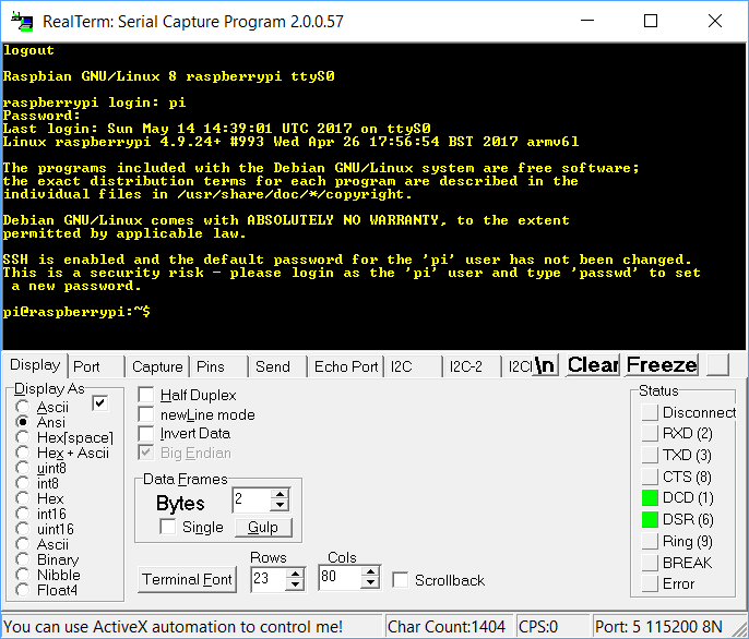
Use mbed as a Pi console cable to run command line Linux
If you have not used mbed's virtual com port before, read these instructions. After powering up the Pi and waiting a bit for the OS to boot, use a terminal application on the PC connect to the mbed virtual com port at 115200 baud and hit enter a couple times to get a logon prompt. Use the ANSI display option on the terminal application, if it supports it. The default password is raspberry. You can logon as pi and type command lines as seen below:

Wiring
| Pi I/O header pin | mbed LPC1768 |
|---|---|
| 6 - gnd | gnd |
| 8 - TX | p10 (RX) |
| 10 -RX | p9 (TX) |
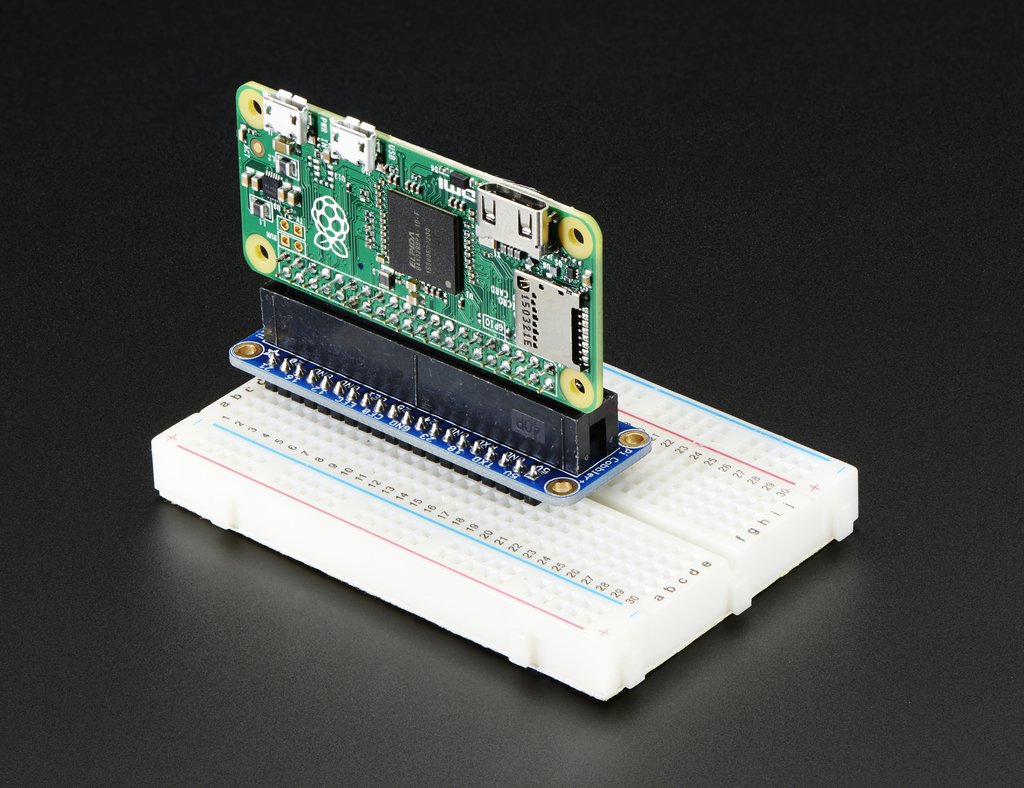
There are various connector options available for Pi I/O header pins for around $10 that will make it easier to make the connections needed. The one below from Adafruit is my favorite setup for Pi zeros in a breadboard. Even the header pins have to be purchased separately and soldered on. This setup uses a right angle female header and Adafruit's Pi cobbler. The cobbler has the I/O pins labeled on the silkscreen. If you need to locate the pins directly, Pi I/O header pin drawings are available.

5V Power
There is not enough power on mbed's 5V pin to power the standalone Pi Zero W (it almost works, but dies during boot!), so another 5V power source is needed. If multiple USB devices are added to the Pi, as much as 5V 2A might be needed. Small AC wall warts with a micro USB connector for around $7 can be used to power the Pi. If the Pi is on a breadboard, just hook up any 5V DC supply. Some micro USB phone chargers will also work. The green LED on the Pi is an activity LED that turns on during boot. To see the green LED come on, it needs power and a uSD card inserted that starts to boot.
Remote GUI Access with VNC
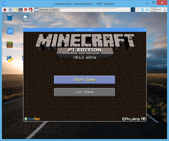
If you have a console cable, you can use the command line to setup your network connection, enable VNC (Virtual Network Computing), and get the Pi’s IP address using hostname -I. With networking and VNC setup, any PC or even a smartphone can run the Pi’s desktop GUI interface remotely over the network using a VNC viewer app. So no HDMI monitor, HDMI cables, or USB hub with a keyboard and mouse is needed to run the Pi’s GUI interface. This can save another $20+ of cables, if you don’t have them.

The Pi GUI running on a PC using VNC with the network
Pi I/O versus mbed I/O
I/O on the Pi is a bit limited, slow, and not as easy to use as mbed. For example, there is only one PWM output available on the I/O header and the user needs to scale all values to integers to use it. Some Pi I/O examples use Python, but it can run up to 100 times slower than C when used for low level I/O. There is a BCM2835 I/O library for C/C++ on the Pi, but it is really an older C-style approach with complex function calls needed for everything, a lot of complex #define names you need to know for constants, and it has to run with super user privileges. Code can be compiled on the Pi using the command line or by using the the geany GUI IDE (need to add it to the base OS after install and update). The good news is that with millions of Pi boards in use, Linux tends to have fewer bugs than on other embedded boards.
Here is a basic Pi I/O example that sets up and toggles a GPIO bit as fast as possible:
#include <bcm2835.h>

#define PIN18 RPI_GPIO_P1_12

int main(int argc, char **argv){
	if(!bcm2835_init())return 1; /* Initialize */
	bcm2835_gpio_fsel(PIN18, BCM2835_GPIO_FSEL_OUTP); /*Sets PIN18 to output*/

	while(1){					 /* Forever loop */
		bcm2835_gpio_set(PIN18); /* PIN18 = high */
		bcm2835_gpio_clr(PIN18); /* PIN18 = low  */
	}
}
On mbed, the same code is a bit simpler and easier to write:
#include "mbed.h"

DigitalOut mypin(p6);

int main()
{
    while(1) {
        mypin = 1;
        mypin = 0;

    }
}
There is also a newer alternative I/O library for the Pi, wiringpi that works in a similar way. It has somewhat similar function calls, but renumbers all the pins in a different way. It has a few more features and a command line interface to try things in addition to C/C++ I/O APIs. It might be a better in some cases. It has a function to use the serial port.
For some projects, it might make sense to use both the Pi and an mbed. Broadcom will not release full details on the processor and I/O hardware without an NDA, so it can be hard to do new things unless example code is available. They also don't sell the chips directly, so getting some to build your own board is an issue. Pi boards can be used in products to sell, but at times they are in short supply.
Real Time Issues: Linux versus RTOS
Keep in mind that a lot of other processes and threads are running in Linux on the Pi, so it is possible to get an occasional OS time slice interrupt in your code and not return for 10 ms. or more even under light loads - a lot longer than an RTOS by perhaps an order of magnitude or more. This happens somewhat infrequently, so it might take a logic analyzer looking for this event to capture it. Pis with multiple cores and using priorities will help this issue a bit.
This is such an issue with Linux (or any general purpose OS) that some processors, such as the one on the BeagleBoard Black, add a microcontroller or two (called PRUs by TI) to handle low-level real-time I/O tasks in a deterministic way. They are a bit difficult to use and program, and the mbed could also be used for such tasks. Even smart phones and tablets have several microcontrollers in addition to the main processor. There is also an added benefit of the main processor gaining additional time to run applications when microcontrollers perfrom low level I/O tasks.
Pi and mbed projects
The USB virtual com port can be used to communicate between the pi and mbed. An mbed example is available along with the C++ code needed for the pi. On the Pi, the typical device name is "/dev/ttyACM0" for the virtual com port.
Here are some student projects using both a Pi and an mbed:
Paparazzi-bot
TJbot riding a robot
Spybot
The USB virtual com port is used for Pi from/to mbed communications with the mbed plugged into a Pi USB port. It would also be possible to use both devices (real) serial ports for communications. The Pi is using WiFi to contact a cloud server for speech and image recognition in the first two projects, and the mbed is doing lower level I/O operations on a robot. In the last project, a Pi zero W with a Pi camera is used to stream video to a web page, and the mbed controls the robot with a Bluetooth remote control link.
BeagleBone Black Console Cable
The same mbed console code should also work on the BeagleBone Black for a console cable since it also uses a 115200 baud serial interface. J1 has the pins for the serial console. Since it has pins, 3 M/F flexible jumper wires will be needed for hookup. The Cloud9 IDE is typically used to develop code via the USB connection to a PC. VNC can also be used on the BeagleBone Black. Newer BeagleBone boards have the console pins on a different connector.
Wiring
| BBB J1 | Function |
|---|---|
| Pin 1 | Ground |
| Pin 4 | RX |
| Pin 5 | TX |
Please log in to post comments.
