Using a Photocell or Phototransistor to determine lighting levels
Many embedded devices need to detect light levels. A low-cost photocell can be used to determine different lighting levels in a room. The photocell seen below can cost under $1 and is available from Adafruit or Sparkfun. The resistance of this type of a photocell (also known as a photoresistor or light dependent resistor (LDR) ) varies with the light level on top of the sensor. Photocells are more sensitive to red and green light levels and not very sensitive at all to blue. A common application would be to dim an LED automatically in a dark room and brighten it when it is in full daylight so that it is visible, or perhaps just turn on the light when it is dark. The resistance response can vary quite a bit from photocell to photocell (perhaps as much as 50%), so extremely accurate light level measurements are not possible without individual calibration for each photocell.
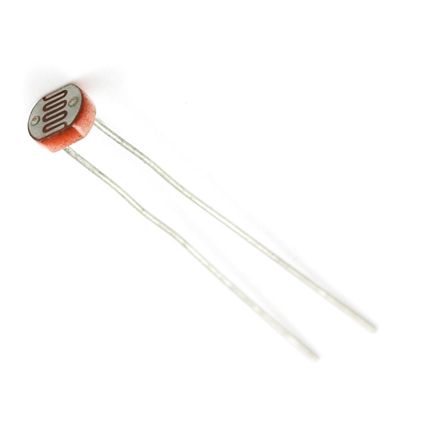
A typical CdS Photocell from Sparkfun
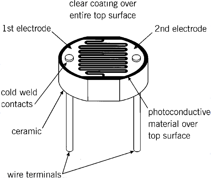
Internal Structure of Photocell
Wiring
The easiest way to hookup this device is to use a voltage divider circuit connected to an analog input pin. The resistance of the device changes based on the lighting level (light levels are measured in lux). This low cost device can measure approximate lighting levels and that is all that is needed in many applications.

Schematic of Photocell hookup to an analog input
The typical way to interface this device is to hook it up to the 3.3 supply and use a 10K pulldown resistor to build a voltage divider circuit as seen in the schematic above. An A/D is then used to read the analog voltage value into the microprocessor. The resistance values and voltages shown in the table below are for the photocell from Adafruit. The photocell from Sparkfun is very similar, but the datasheet lists a maximum dark value of 1MΩ. Note that the analog voltage response is not linear (closer to a logarithmic response), but it is monotonically increasing. To expand the high light-level readings or for a different photocell, the pull down resistor value may need to change a bit to get the maximum analog voltage swing. A rough rule of thumb for this is Rpd = (Rmin*Rmax)1/2, where Rmin and Rmax is the region of interest to measure.
| Light level | Ambient light (lux) | Photocell resistance | Voltage across R1 |
|---|---|---|---|
| Moonless cloudy night - rural area | .0001 lux | >0.2 MΩ | <0.15V |
| Moonlit night | 1 lux | 70 KΩ | 0.412V |
| Dark room | 10 lux | 10 KΩ | 1.65 V |
| Dark overcast day / Bright room | 100 lux | 1.5 KΩ | 1.34 V |
| Overcast day | 1000 lux | 300 Ω | 3.2V |
| Full daylight | 10,000 lux | 100 Ω | 3.26V |
| Direct Full Sun | 100,000 lux | <100Ω | >3.26V |
By checking the value of the analog voltage by using the AnalogIn API on mbed, the light condition can be detected. Recall that the mbed AnalogIn API scales the voltage from 0.0 to 1.0 with 1.0 being an external analog input voltage of 3.3V.
Example Program
An example program is shown below for the photocells analog output connected to p15 on the mbed LPC1768 using the schematic seen earlier. As the room gets darker, the photocells analog voltage output drops and a PWM output is used to dim one of mbed built-in leds. You can place your finger over the top surface of the photocell to simulate the room getting darker. A cupped hand actually works a bit better since it also blocks light from the sides and bottom. A similar idea is used to automatically dim the back light leds on mobile device displays to save power and keep them from being too bright in a dark room but still keeping them visible in daylight. Large outdoor signs also do this and some communities even have local ordinances enforcing this to reduce urban light pollution at night.
#include "mbed.h"

AnalogIn photocell(p15);
PwmOut myled(LED1);
//photocell analog input dims led at lower light levels using PWM
int main()
{
    while(1) {
        myled = photocell;
        wait(0.1);
    }
}
Other Light Sensor Options
It is even possible to use an LED to detect bright light, but a transistor amplifier circuit will likely be needed since the voltage and current output from the LED is very low. It is simpler just to use a phototransistor instead. The base on a phototransistor is controlled by the external light that shines through its transparent package, so a phototransistor only has two external pins.
While the long leads make the photocell breadboard friendly, in an actual device a tiny surface mount phototransistor type light sensor with a resistor would likely be used. A large number of such options are available. These are often used to dim the display backlighting on phones, tablets, and notebook PCs. These would require a breakout board for breadboard use. Sparkfun and Adafruit have several such breakout boards for a few dollars more than the basic photocell option used here. Some also feature more precise measurements than are possible with a photocell. Photocells do have a higher voltage rating (perhaps 150V) allowing them to be used directly in triac or relay AC lighting control circuits (unlike a phototransistor). CdS photoresistors are now banned in Europe (RoHS) and silicon phototransistors must be used instead.
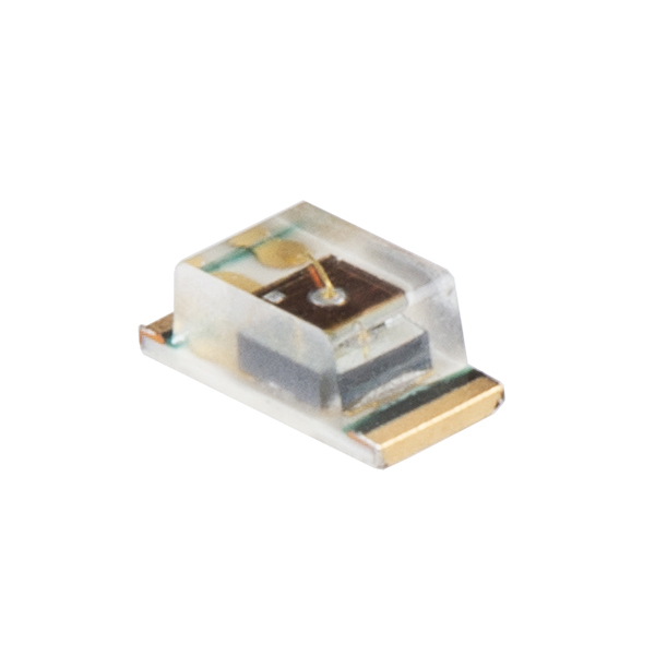
Surface Mount ALS PT19 Light Sensor
A phototransistor supplies light-level controlled current to a series resistor and the voltage drop across the resistor is measured using an A/D, so it is very similar to the earlier photocell hookup. Unlike the photocell, the two phototransistor pins have polarity. The earlier demo program will also work for a phototransistor. Since it is a bipolar transistor, there will be a voltage drop across the transistor and the circuit's analog output voltage swing will be reduced a bit.
When more accurate light readings are needed (or even the exact color!) other light sensors are available at an increased cost. Some even have a digital I2C interface with red, green, and blue sensors.

Typical Phototransistor Interface Circuit
There are a couple of low-cost phototransistors with wire leads (i.e., not surface mount) for use directly in a breadboard. They look a bit like an LED as seen below.
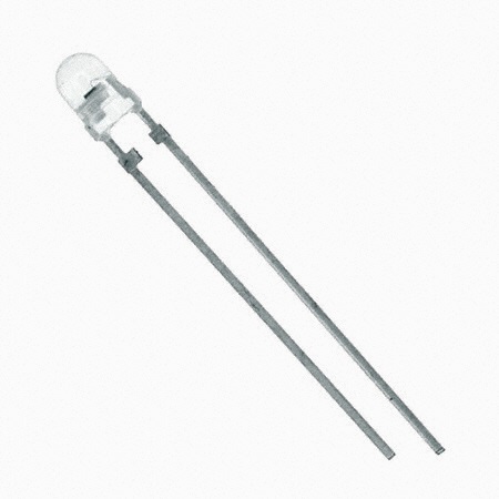
Phototransistor in a through hole package
Phototransistors are even combined with LEDs in a single package to detect objects. The light from the LED reflects from an object, or is interrupted by an object and the phototransistor detects the presence or absence of the LED light. Line following sensors on robots use this type of device.
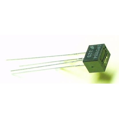
This IR detector from Sparkfun contains an LED and Phototransistor
Typical Applications
Common applications include automatic dusk to dawn outdoor lighting such as streetlights, automatic night lights, automatic camera exposure control, automatic brightness control on displays, automatic car headlights and rear view mirrors that dim, and office building lights. Modern office buildings with large windows often have a circuit to dim indoor lighting in the daytime during periods of bright sunlight. This not only reduces the power consumed by the lights, but it also reduces cooling costs.
Additional Resources
Please log in to post comments.
