Using a Brushless DC motor with an RC ESC
Brushless DC motors
Brushless DC motors are smaller and weigh less than equivalent DC (Brushed) motors, but they require a more complex speed control circuit. Brushless DC motors are used in most drones and they typically have 3 wires instead of 2. Another advantage is that they don't have the constant electrical arcing of a regular DC motor's commutator, so they also generate a lot less RF electromagnetic interference than a low-cost DC motor. The electronic speed control (ESC) circuit needs a microprocessor with PWM outputs and three power MOSFET half-bridge drivers (two transistors each to drive a pin high, low, or not connected) to drive the three motor windings as seen in the block diagram below.
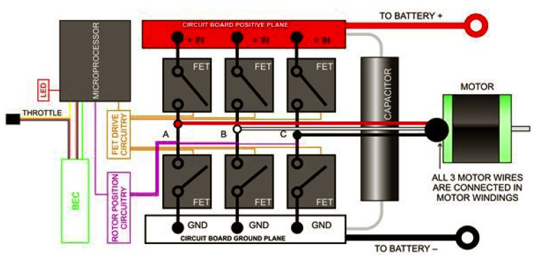
Firmware can sense the motor’s back EMF on one of the three coils and eliminate the need for an encoder to generate the correct sequence and timing of the PWM output signals. The PWM outputs generate a three phase AC-like signal for the motor using a DC power supply (battery). Some high-end brushless DC motors also have encoders. The speed control input signal (i.e., throttle) used in most ESCs for drones works the same as standard RC servo signals, a 1-2ms. wide pulse every 20ms. Some ESCs also include a BEC (Battery Eliminator Circuit) that can power the RC receiver using the same battery as the motors, but with a bit more regulation to reduce noise from the motors on the power supply.
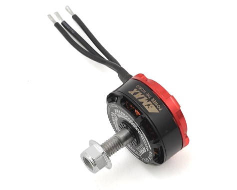
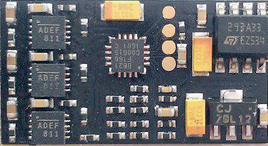
A brushless DC motor for drones with an electronic speed control module.
Helloworld Demo
RC ESC modules and brushless DC motors are mass produced for the hobbyist market and are low cost. The setup used here runs around US $35. RC ESC modules use the same PWM signals as RC servos. The mbed servo class is used to send the PWM signal to control the motors. The tricky bit is that ESCs require a special startup calibration and arming sequence. The ESC uses the motor to send beep codes at power up and during the arming procedure. When the ESC powers up, three beeps sound. Next, a full throttle signal is sent, followed by a low throttle. On an RC radio control module, the user moves the stick up, waits for a beep code and pulls the stick down all the way followed by another beep code. In the mbed code, time delays were added to simulate the user waiting for the beep codes.
This ESC uses the BL_Heli_S firmware that requires a microprocessor with three hardware PWM bits for smoother speed control. The PWM clock is 24Khz and 2048 different PWM values are used. Some new ESC modules with BLHeli 32 use 32-bit ARM cores with a PWM clock of 48Khz and faster options than the standard 20ms RC PWM update rate. Telemetry from the motor ESC such as RPM, current, and temperature is available on some BLHeli 32 ESCs. Older ones often have 8-bit 8051 based processors. The ESC module would not operate on only 5V DC. An old 9VDC 1A wall wart was used in the demo. In drones, rechargeable Lithium battery packs provide power since they have a higher energy density than other batteries. The control signal to the ESC is optoisolated. The motor used in the demo is rated at 2600 kV. In the case of brushless DC motors, kV means RPMs per Volt (not kilovolts!).
Wiring
| mbed | ESC module | Brushless DC motor | Motor Power Supply/Battery |
|---|---|---|---|
| gnd | black servo cable wire | ||
| p21 | white servo cable wire | ||
| black motor power wire | gnd | ||
| red motor power wire | around 7.4-14.8 VDC 2A | ||
| (2S to 4S LiPo battery pack) | |||
| Three small solder pads | Three motor leads |
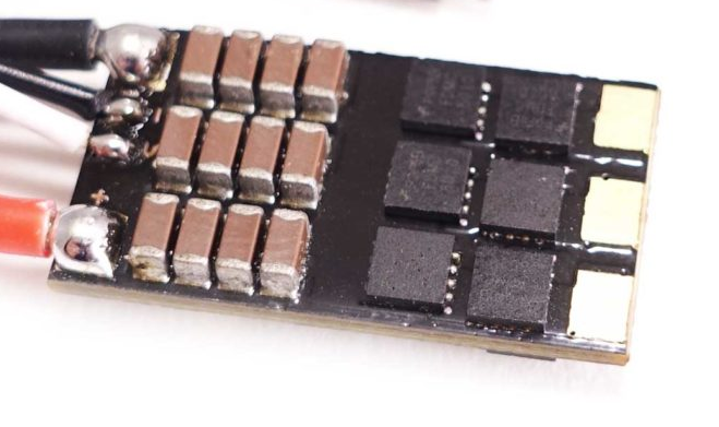
Backside of ESC board with six MOSFETs and lots of caps. Motor solder pads on right.
Safety Note
The propeller is moving so fast that it can cut your finger it you get near it!
This high-speed video shows one slicing through a large piece of pork!
Note: The motor is so small and powerful that it will be necessary to mount it for testing (even without a prop)! A quick stop will twist all the cables into a tight braid without a mount. Since the black outside case of the motor rotates, it is hard to hold with your hand. There are four threaded screw holes on the back of the motor case and the motor comes with screws for mounting. The center of the backside of the motor rotates, so it needs a large center hole when mounting.
By swapping any pair of motor leads at the ESC or changing the software configuration of the ESC, the motor will rotate in the reverse direction. They can even be setup for bidirectional operation, so that inverted flight is possible. Drones with 4 motors have the two pairs of diagonal motors rotating in the opposite direction to minimize rotational torque on the airframe which keeps it a bit more stable and easier to turn. CW or CCW refers to the direction of the shaft threads. The prop nut is less likely to spin off if the threads are opposite the motor rotation.
The mbed motor test stand demo. With a few holes, this board would fly!
To run the demo code, power must be turned on to the motors first (it sends three beeps at power up). Next power up the mbed (or release the reset pushbutton, if it is used instead of a power cycle).
// Calibrate and arm ESC and then sweep through motor speed range
// To run: Hold down reset on mbed and power up ESC motor supply
// Wait for three power up beeps from ESC, then release reset on mbed
// See https://github.com/bitdump/BLHeli/blob/master/BLHeli_S%20SiLabs/BLHeli_S%20manual%20SiLabs%20Rev16.x.pdf
// for info on beep codes and calibration
#include "mbed.h"
#include "Servo.h"
PwmOut ledf(LED1); //throttle up test led with PWM dimming
PwmOut ledr(LED2); //throttle down test led with PWM dimming

Servo myservo(p21);

int main()
{
    myservo = 0.0;
    ledf = ledr = 1;
    wait(0.5); //detects signal
//Required ESC Calibration/Arming sequence
//sends longest and shortest PWM pulse to learn and arm at power on
    myservo = 1.0; //send longest PWM
    ledf = ledr = 0;
    wait(8);
    myservo = 0.0; //send shortest PWM
    wait(8);
//ESC now operational using standard servo PWM signals
    while (1) {
        for (float p=0.0; p<=1.0; p += 0.025) { //throttle up slowly to full throttle
            myservo = p;
            ledf = p;
            wait(1.0);
        }
        myservo = 0.0; //Motor off
        ledf = ledr = 0;
        wait(4.0);
        for (float p=1.0; p>=0.0; p -= 0.025) { //Throttle down slowly from full throttle
            myservo = p;
            ledr = p;
            wait(1.0);
        }
        myservo = 0.0; //Motor off
        ledf = ledr = 0;
        wait(4.0);
    }
}
Import programESC_DC_Brushless_motor_test
Runs an RC Brushless DC motor using with an ESC module. Mbed supplies the PWM control signal for the ESC. See https://developer.mbed.org/users/4180_1/notebook/using-a-dc-brushless-motor-with-an-rc-esc/ for more info
Applications
FPV (First Person View) Racing drones use live video feedback from a camera and can reach speeds near 150 MPH. This motor and speed control can be used in mid size racing quadcopters like the one seen below:
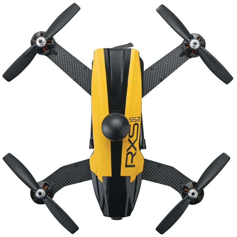
An FPV Racing Drone with four brushless motors and ESCs.

High-end RC cars and boats use larger brushless motors and ESCs such as the 4000KV 70A setup above. They can reach speeds over 70 MPH. Some motors and ESCs are even waterproof.
Here is an mbed student project using one of the motors and ESCs to build the lift motor for a hovercraft:
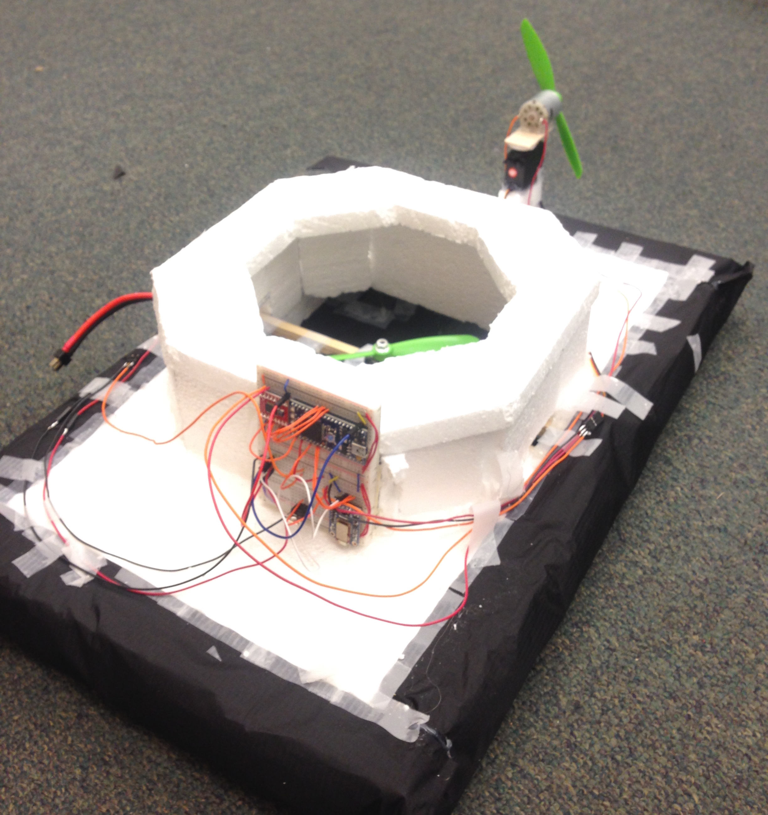
Here is a video of an mbed controlled quadcopter:
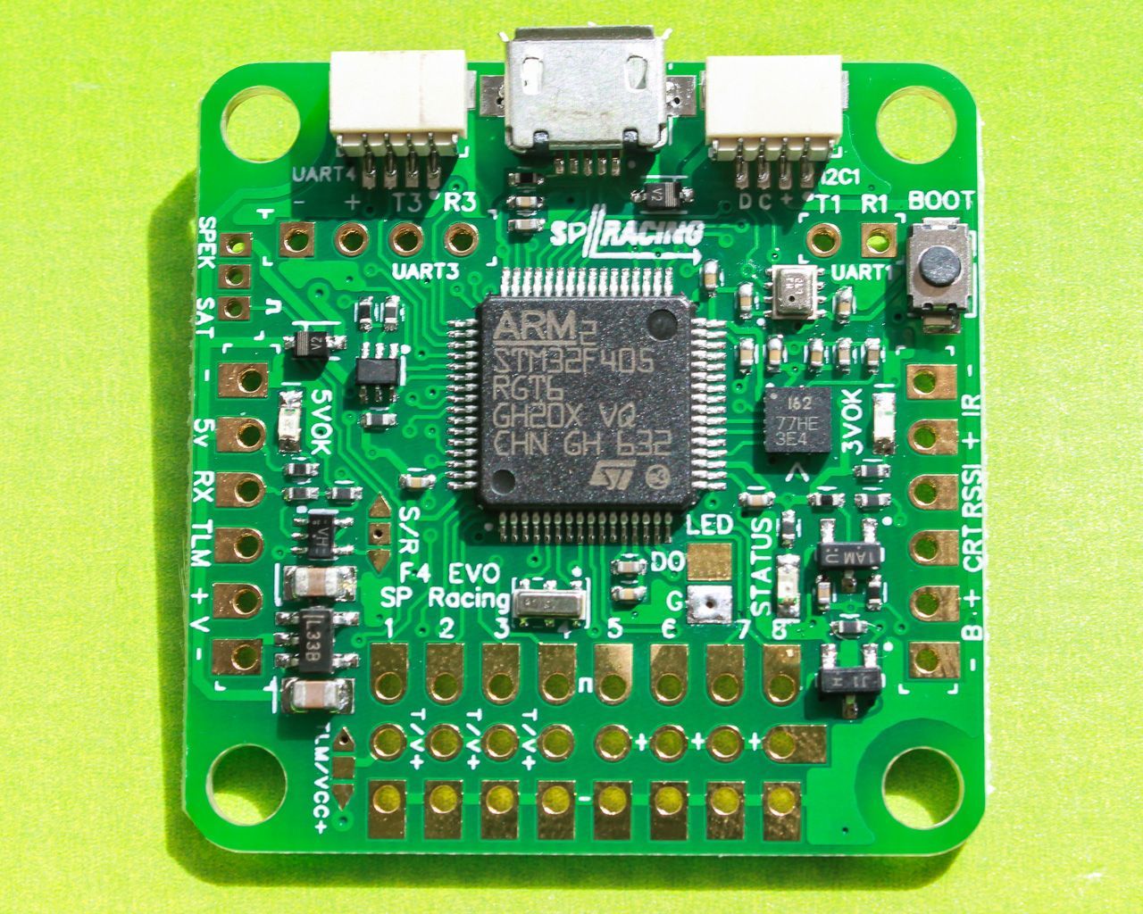
On quadcopters, a flight controller module with a gyro, accelerometer and perhaps a compass, GPS and Sonar is used to stabilize the copters attitude and perhaps even altitude. Without a flight controller to stabilize the copter, it will quickly spin or tumble out of control faster than a human pilot can respond. The user’s remote control radio transmits control inputs to the radio receiver module and the receiver passes user control inputs to the flight controller. The flight controller drives the ESC modules while keeping the copter stable. When a flight controller is upgraded with a magnetometer (compass), GPS, barometric sensor (altimeter) and perhaps an air speed sensor it becomes capable of autonomous flight and navigation. This type of device is often called an autopilot. Most flight controllers run an RTOS and floating point hardware is useful to speed up control loops. A small flight controller module, a SP F4evo, is shown below with an ARM Cortex M4 core. Four ESCs are available on one board the same size for quadcopters (called a 4 -in-1 ESC).
ESC Options and Programming
It is also possible to program many options and parameters on the ESC. This can be done using the control sticks with feedback beeps, or using a GUI on a PC with a microcontroller sending data to the ESC. Some ESCs can also work with I2C or Serial signals in addition to PWM. Hard core drone racers spend a lot of time tuning engines.
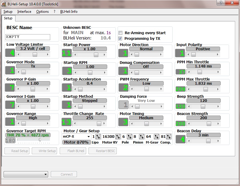
BLHeli software talks to the ESC using an FTDI cable to adjust motor settings. The mbed “FTDI-style” program and setup below was used with BLHeli to reprogram the ESC’s motor settings using the GUI when connecting to the mbed’s USB virtual com port at 19200.
Import programBLHeli_FTDI_Cable
Used to tune ESC controllers using BLHeli firmware
BLHeli Suite Wiring
| mbed | ESC | Diode |
|---|---|---|
| gnd | black servo wire | |
| p10 RX | white servo wire | + |
| p9 TX | - (band) |
NOTE: Power must be cycled on the ESC after writing new values before they take effect.
In addition to the Windows GUI app shown above, there are new apps available for Macs, Linux, and Android to program the BLHeli ESC. It is also possible to program the ESC to play music using the motor with the app.
Interesting Drone Videos
Drone racing: First Person View (FPV)
A Recent Drone race with a prize of $1,000,000
Bad ways to use drones
Drone Motors being assembled and tested at a factory in China
Other Small Brushless DC Motors
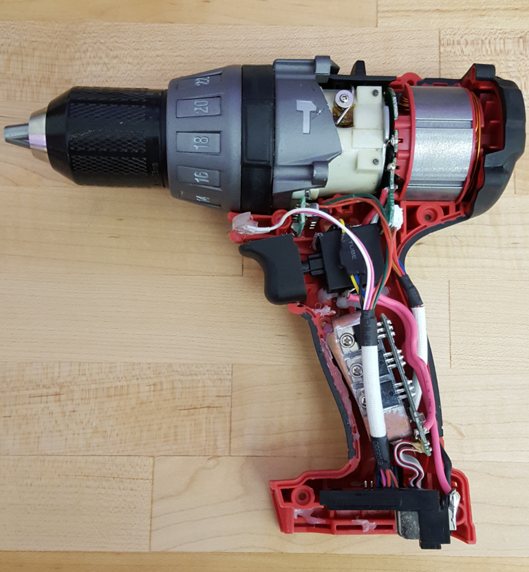
Modern mid to high-end battery operated hand tools such as drills and electric screwdrivers now contain a brushless DC motor and ESC module with an SoC processor as seen above in this Milwaukee Tool Drill. The ESC and MOSFETs can be seen in the small PCB located inside the handle. Currently, many of these tools use several Hall effect sensors near the rotor magnets for feedback. This approach provides more control at low speeds than sensor less motors like those used in high speed drone motors to drive propellers. One advanced electric screwdriver even allows a Bluetooth connection from a phone app to download the optimal drive speed and torque curves depending on the exact screw and material being used. Some large tools used in dangerous applications can even be remotely controlled using Bluetooth to ensure operator safety. Peak current on large hand tool motors can approach 200 amps.
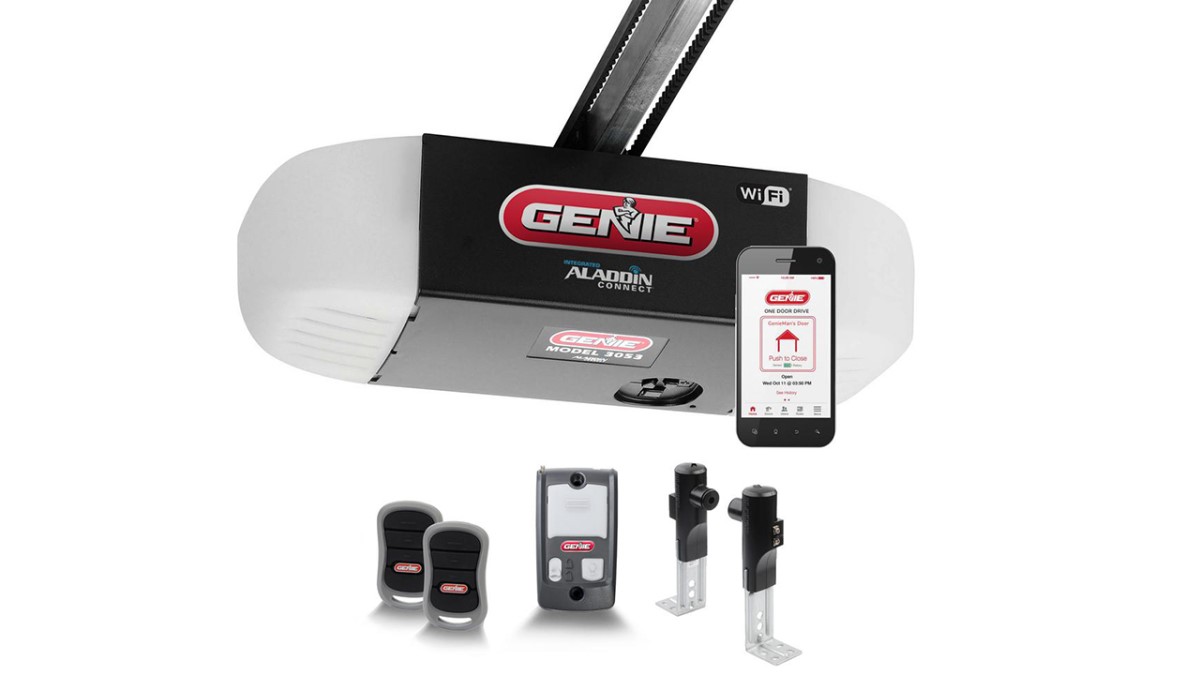
One of the latest advances in home automatic garage door openers is the addition of battery backup (CA law), a brushless DC motor, large LED light, wireless RF in car remotes, and WiFi IoT control from a smartphone through a cloud server. Traditionally, garage doors use a single pushbutton for a user interface and newer ones add an LCD for status. Hitting the button opens or closes the door (whichever is needed) and if the button is hit while the door is moving, it stops the motor. If the button is hit after a stop, the direction is reversed. Older doors use two digital limit switch inputs (i.e. like a pushbutton the door hits) that indicate when the door is all the way opened or closed. Some new doors use motor feedback to sense opened or closed. To avoid crushing small children and pets when the door closes, an IR sensor beam sent across the bottom of the door stops the door, if something is in the way.
Other Induction Motors
Brushless DC motors are one type of induction motor. Most large industrial motors are AC induction motors with a three phase AC drive signal. AC induction motors were invented by Tesla around a century ago, but speed control using electronics is relatively new.
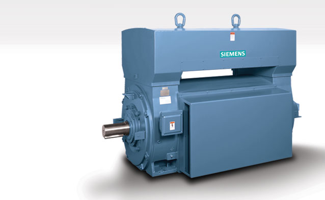
A large Siemans Industrial Motor
The speed controller for a large industrial motor is very similar in principle to an ESC and PWM outputs are produced for control signals, but six large IGBTs are typically used instead of MOSFETs to provide the large currents and voltages required. Instead of an ESC (term common in RC hardware), it is called a variable frequency drive (VFD). In addition to speed control, VFDs can save significant energy.
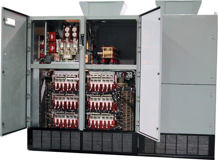
A Popular Toshiba VFD system used for large industrial motors
Linear Induction Motors
A Linear induction motor (LIM) repeats the coil pattern in a linear sequence. LIMs provide linear motion instead of rotary motion. An tiny linear induction motor is seen in the video below of a nano scale model train.
This is a Nano scale (1/1000th) model train set from teenytrains.com. It is built using a linear induction motor. On the PCB, a microcontroller with firmware (covered by black goo dot) generates the three phase timing signals to drive the motor. Six power transistors (three half-bridge drivers) use PWM control signals from the microprocessor to drive the three coil circuits. The motor's coil circuits (tiny traces with round patterns seen on track PCB) repeat around the track. Each train car has four small neodymium magnets. Note that the drive circuitry is very similar to the ESC used to control the brushless DC motor earlier although the speed control firmware is a bit different (i.e., frequencies are a lot lower).
LIMs are also used in the maglev technology being developed for high-speed trains such as Japan’s 600KPH Bullet Train.
LIMs are also used in high-end sliding doors and gates such as the system seen in the video below. It elminates the need for mechanical drive parts such as belts, gears, or chains which wear out over time.
The world's most powerful LIM was recently used to replace the steam driven catapult on an aircraft carrier. Steam has been used for almost a century to launch planes. According to reports, the energy developed by this motor could throw a Volkswagen ten miles.
Diesel Electric Locomotives use six large motors with a VFD-like drive system. The Diesel engine runs an alternator for motor power.
Each of the six axles has an induction motor. Induction motors with a VFD drive system can haul almost twice the load as the older DC traction motors. The electronic drive system allows the wheels to run just below the point where they would slip, and it also distributes the load between wheels more evenly.
Higher End Electric Skateboards and Scooters use a large brushless DC motor, rechargable batteries that support a high discharge rate, and a larger ESC module with a microcontroller.
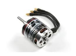
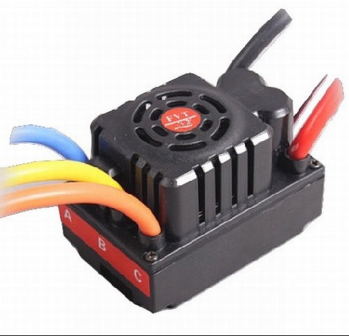
The larger brushless DC motor and ESC module above can support motor operation at around 44V and 80 amps from LiPoly batteries.
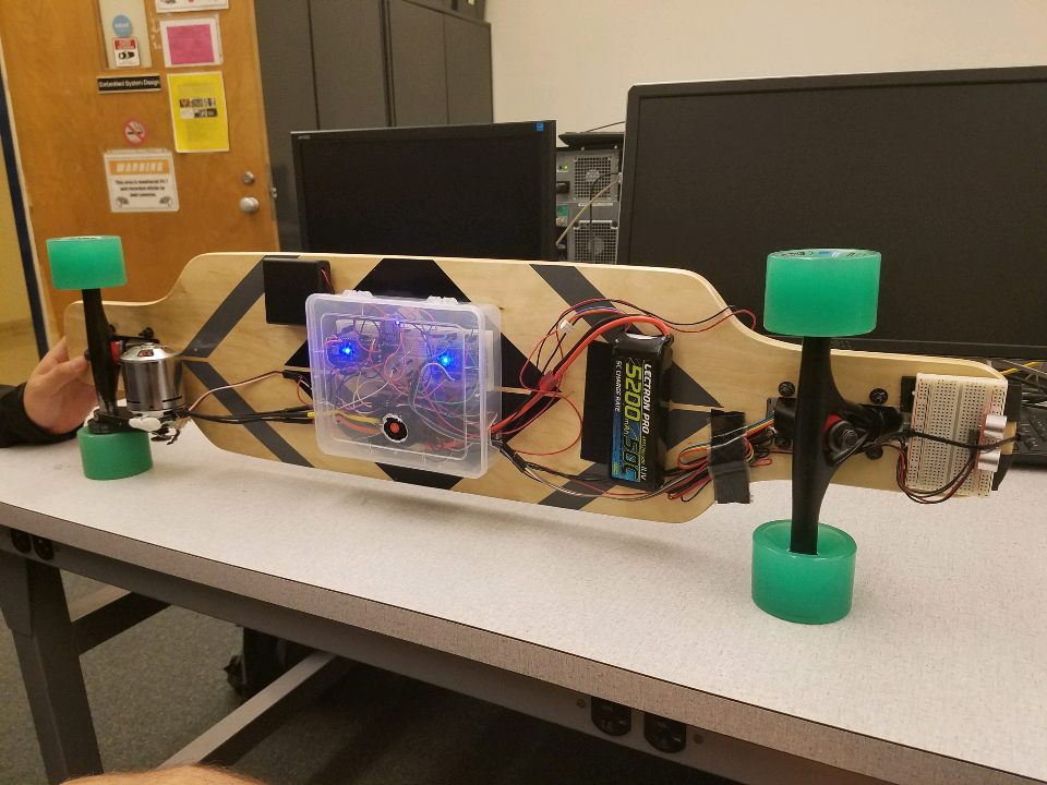
This is an mbed student project below with these parts added to a skateboard. A Bluetooth module allows remote control of motor speed using a phone and it has a kill switch in case you fall off. A Sonar stops the motor when an obstacle is detected and an LCD module indicates speed and battery charge state. Add on parts are available to upgrade your skateboard and the motor just bolts on with a belt drive, but it costs a bit over $300.
If you develop your own battery and charger system, be aware that Lithium batteries can explode and/or catch on fire if they are overcharged, overheat, shorted out, have damage such as a dent, or internal manufacturing defects. Use quality batteries and avoid simple charger circuits that can overcharge batteries, if left plugged in too long. The video below shows what can happen!
Electric Scooter Battery Explosion!
Electric Car Tutorial. In hybrid cars, the speed control circuit is called an inverter.
1 comment on Using a Brushless DC motor with an RC ESC:
Please log in to post comments.

please visit us my website thanks for more result https://thailotterysures.com/