I2C Debug for RealTerm
How to use the I2C Debug feature for RealTerm
Many I2C devices are complex and not completely explained in the datasheet. Often times you need to experiment a bit with the device to figure out exactly how it works before writing a final version of the code to communicate with the device. This tool can help at that early stage in development.
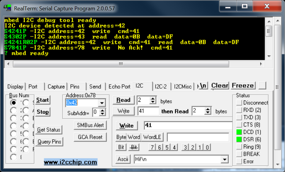
RealTerm is a free Windows Terminal application program with some hardware debug features. RealTerm has an I2C command tab designed to be used with a hardware module made by www.i2cchip.com. This program runs on mbed and takes the place of the hardware module by reading the ASCII commands strings from RealTerm over the mbed's USB virtual com port, and then calling the mbed I2C APIs for the desired I2C read and write operations. In the image below, you can see it talking to the Honeywell HMC6352 I2C compass module. Yellow text comes from mbed, and the green text strings are the ASCII command strings sent by pushing the I2C GUI buttons in RealTerm. Instead of RealTerm, you could use any terminal application program by typing the character strings in green, but the GUI buttons are faster.
Import programI2C_Debug_for_RealTerm
I2C debug program for use with RealTerm. Sends I2C commands to P9 and P10. Run program on mbed. Start RealTerm, select the mbed virtual com port under the port tab, then open RealTerm's I2C command tab. Reset mbed. See http://mbed.org/users/4180_1/notebook/i2c-debug-for-realterm/ for instructions

I2C Debug Program for RealTerm Talking to HMC6352 I2C Compass
When the program starts, it scans all 128 I2C addresses checking for an acknowledge back in response to a read byte command. In this case, only one device responds at address 0x42. Then, you need to select the I2C address of the device in the "Address" box. In this case, it is 0x42 from the HMC6352 datasheet or the scan address response. Then by selecting the "Write" or "Read" GUI buttons, an I2C write or read operation can be performed. In the first command line, a command of 0x41 is sent using the "write button" which tells it to take a reading. In the second command line, a "read button" operation then reads back a two byte compass heading in tenths of degrees. In the third command line, the "write then read button" does both with one button. In the last command line, the I2C address was changed to an invalid address of 0x78 and when no I2C device is there to respond with an ack to a write, it prints "No Ack!". Last, the get status button is pushed and the mbed responds with "mbed ready". The I2C device is setup to use p9 and p10. It can easily be changed to another I2C port with a code edit.
5 comments on I2C Debug for RealTerm:
Please log in to post comments.

I downloaded reaterm ver 1.99.0.27 but I'm wondering where I can get ver 2.0.0.57 as illustrated. I have a DS1307 real time clock which I'd like to understand. I got the TMP102 chip to work easily enough but the DS1307 has a lot of registers to read and I cant be sure what I'm reading.I've managed to see it using realterm and found the default address D0. After that I'm a bit in the dark.Here is a snapshot of the datasheet and please could you tell me how to read the current time or date and I'll proceed from there. /media/uploads/GregMartin/ds1307memory.doc /media/uploads/GregMartin/realtermpic.doc