Controlling a Model Railroad using mbed
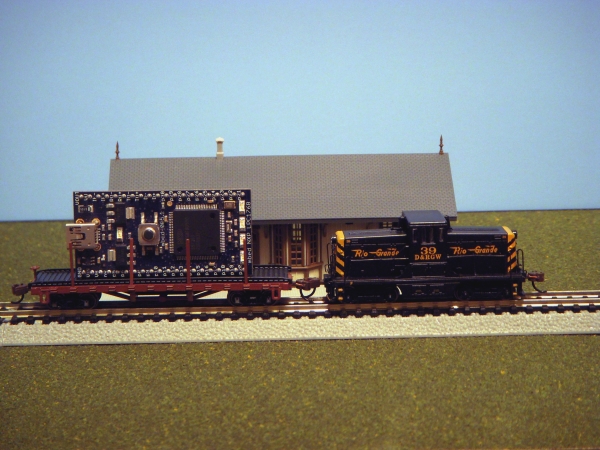
N Gauge Model Train
With just a handful of additional low-cost parts it is possible to control a model train set using mbed. This tutorial shows how to get started with a basic overview of model train technology, simple hardware interfaces, and some code examples.
Controlling a DC (Analog) Train Engine
An entry level model train set contains an engine with DC motor and the power is provided by the two track rails. PWM is the easy way to control speed on a DC motor. By reversing the power connections to a DC motor with an H-bridge it can be reversed. With an H-bridge driver using PWM both speed and direction of a DC motor can be controlled.
Many track accessories such as lights and track switches (i.e., a turnout) also use AC power from the track. So ideally, the track voltage output should have both a DC and AC level. Some setups use a separate AC power connection for accessories, but it is a bit easier to use AC from the track if it is present. 12 volts will run the smaller gauge trains and the larger ones need a few more volts.
Parts needed
First, a DC power supply is needed in the range of 12-22 volts. On N gauge, an old 12 volt power supply from a PC or any 12 volt DC AC wall wart can be used to drive the train control circuit. If the train set came with a DC manual controller, just set the throttle to full and the output should be around 20 volts DC (double check with a Volt Ohm meter first to get the polarity correct!) so it can be used as a DC power supply. The throttle will adjust the output voltage.
The second part needed is an H-bridge driver breakout with the correct voltage and current ratings. The voltage rating should be higher than the supply and the continuous current rating should be about the same as or perhaps more than the DC supply. Some devices also assume a heatsink is being used when giving maximum current ratings. Around 1 amp will run a couple small N gauge trains. In some cases, the two circuits in a dual H-bridge can be connected together to double the current rating. Track shorts can occur in a derailment or something metal could be dropped across the track, so an H-bridge with a short circuit or thermal protection circuit is probably a good idea.
The H-bridge circuit is always running in forward or reverse mode (for AC) and it is much easier to connect a logic inverter for the reverse input so that one mbed PWM output can drive the entire circuit. An mbed PWMOut pin is connected to the H-bridge forward input and the inverter drives the reverse input. If the H-bridge has a separate PWM input pin, it is connected high. Some new H-bridge circuits already have this feature built-in with a single direction input pin and they would not need an inverter. For the inverter, a 3.3V logic inverter chip could be used or it could be built using a discrete transistor and a couple resistors.
The DC/AC level and train speed is controlled by changing the mbed PWMOut duty cycle. To ensure enough AC to power accessories and to limit motor voltage, the PWM duty cycle should range between 10-90% (.1 to .9 on mbed API). A duty cycle >.5 moves the train in one direction and <.5 moves it in the other direction. Some people like the engine hum from low frequency PWM, but it could be boosted into to the ultrasonic range for quieter operation.
Prolonged operation of some small N and Z scale engines above 13.8V DC can reportedly cause them to overheat and fail. If this is the case with the engine being used, limit the PWM duty cycle in software or adjust the power supply voltage so that this value is not exceeded. When AC is present, some DC engines can even overheat if they are not moving for long periods of time. Some experimentation and double checking the track voltage with a voltmeter will likely be required. The output voltage will drop a bit when it is loaded down with an engine that draws current from the track, so double check this again with an engine on the track. O/S/HO scale engines run about 2 volts higher and large scale adds about 3 volts beyond that. If you only plan on using DC engines (and no DCC engines) and have no accessories that need AC power from the track (or run wires to all of them) the H-bridge could also be setup to turn off just like in standard DC motor control. The code examples here all assume the H-bridge is setup for forward or reverse mode only by using the inverter.
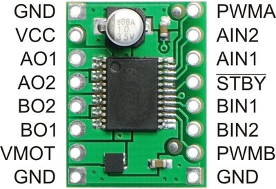
A small MOSFET Dual H-bridge breakout board
Typical H-Bridge Wiring with mbed
| mbed | 12-22V DC supply | H-Bridge | Inverter | Track |
|---|---|---|---|---|
| gnd | gnd | gnd | gnd | |
| Any PWM out | forward | input | ||
| reverse | output | |||
| out+ | track+ | |||
| out- | track- | |||
| Vout(3.3V) | logic Vcc and PWM | logic Vcc | ||
| V+ | Vmot |
On the H-bridge, tie any enable or standby inputs high or low as needed to enable the outputs. This pin could also be tied to an mbed DigitalOut pin and used as an emergency stop to kill all track power.
Bachmann and some other manual train controllers use a standard style audio jack for the track power connection, so if an audio jack breakout board is available, the standard red track power cable can plug into a jack on the breadboard. Two breakouts could be used, one for DC power input and the other for track power output.
Audio Jack Breakout Wiring
| breakout pin | Track |
|---|---|
| gnd | track+ |
| rng | track - |
Warning
Before applying power the first time, double check the breadboard for any shorts from the high voltage DC supply and track outputs to any pin on mbed. 20V will destroy an mbed output pin or perhaps the mbed module. The high voltage supply gnd must also be connected to mbed gnd. It would be a good idea to setup the higher voltage DC supply power bus spaced away from mbed and other low voltage circuits on the breadboard to minimize the possibility of a short or mistaken jumper wire connection.
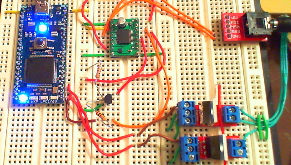
mbed breadboard with H-bridge, two MOSFET drivers for one track switch,
transistor based inverter, and an audio jack breakout to connect track power
Controlling a Switch or Turnout
Most track switches or turnouts contain two solenoid circuits (i.e., a "twin-coil"). One solenoid coil is energized to open the switch and the other to close the switch. These solenoids are only rated for intermittent duty and must be pulsed briefly to move the switch and then left off. Leaving a solenoid on all of the time will cause it to overheat and eventually burn it out. On the bottom right of the image below, you can see the two copper colored coil windings on the solenoid inside the turnout with the cover removed. Three green wires are used, one to each solenoid coil at each end and a common wire in the middle. A short (<1 sec) pulse between 15 to 24 volts is needed on the appropriate solenoid coil to flip the track switch. Some Japanese track switches have only one solenoid circuit (i.e., a 2 wire bipolar control signal +/-) and these would require another H-bridge driver (using forward+, reverse-, and off modes), but these are not as common.
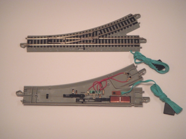
Bachmann E-Z Switch (Turnout) showing internal parts
A driver circuit is needed on an mbed digital out pin to control each solenoid coil. It can be set high and after a short wait (<1 sec) it is turned off. The driver needs a DC supply in the range of 20-24 volts and several hundred milliamps of drive current. The N gauge solenoid in the photo above only moved correctly when the supply voltage was greater than 15 volts. For the demo setup, the Sparkfun MOSFET power switch breakout seen below was used. Two are needed per track switch, one for each solenoid coil.
Outside of China, it is just about impossible to find any connector that fits the green switch wires so it is likely you will need to cut the wire for connections. Extension cables are available and using one would avoid cutting the wire directly attached to the turnout (track switch).The screw terminals on the MOSFET breakout are also very handy to connect the tiny stranded wires coming from the green switch wire. It is probably also a good idea to twist and solder tin each stranded wire to make it more durable. For the other connections needed to the MOSFET, just screw down one end of a short jumper wire and plug the other end into your breadboard.
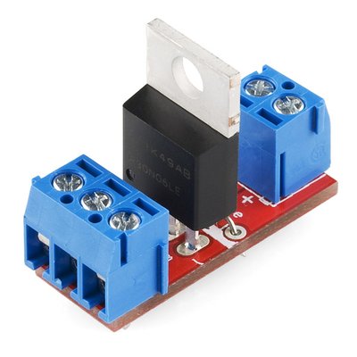
MOSFET power switch breakout
MOSFET breakout wiring (two needed per turnout)
| mbed | 15-20V DC | MOSFET breakout board | Solenoid Coil |
|---|---|---|---|
| gnd | gnd | - pin on three terminal screw block | |
| any DigitalOut | C pin on three terminal screw block | ||
| V+ | + pin on three terminal screw block | ||
| + pin on two terminal screw block | common wire between twin coils | ||
| - pin on two terminal screw block | other wire on coil |
Only one common coil wire connection and V+ connection are needed on the two breakouts
Warning
Once again, solenoid coils can only be turned on for brief periods of time. If left on, the coils can burn out.
With some additional parts, it is possible to setup a circuit that will pulse the solenoid even if the control input remains high. This could happen with a software error or system crash. A 500-2000uf capacitor is connected in series with each solenoid coil. The other end of the coil (the common coil wire) connects to ground. A pullup resistor on the other end of the capacitor (around 1K?) to the DC supply Vcc slowly charges the capacitor. The transistor switch is connected across the series capacitor and coil. When the transistor turns on shorting the series LC combination, a short pulse of high current flows through the coil until the capacitor discharges. This circuit will prevent burning out the coil even if the transistor is left on.
The Automatic Pickle Fork Demo
For an easy to understand demo, a simple track layout with one turnout and one engine was setup. Based on the track shape this is sometimes called a Pickle Fork. The low level code shows exactly what needs to happen at the mbed API and the PWM and DigitalOut hardware level.
#include "mbed.h"
//mbed Automatic Pickle Fork Train Demo
DigitalOut myled2(LED2); //After initial switch test, LED2 blinks to indicate train running

PwmOut Track(p21); //PWM output used to drive track power via H-bridge
PwmOut myled1(LED1); // LED brightness used to indicate PWM duty cycle
DigitalOut Switch1(p22); // driver control output for one switch solenoid coil
DigitalOut Switch2(p24); // driver control output for other switch solenoid coil
int main()
{
    float time=0.0; //keeps track of time for demo
    float start_time = 0.0; //start time for each demo section
    Track.period(0.0001); //set PWM freq
    int lapcount = 0; // counts number of times to flip track switch the other way using even/odd
    Track = 0.5; // set PWM Duty Cycle - used to control train speed and direction
    myled1 = 0.5;
    // reset track switch (turnout)
    Switch1 = 0;
    Switch2 = 0;
    wait(0.25);
    // Switch Demo
    // flip track switch (turnout)
    Switch1 = 1;
    wait(0.5); //only use a very short high pulse for solenoids - might overheat with constant on!
    Switch1 = 0;
    wait(2);
    // flip track switch (turnout) other direction
    Switch2 = 1;
    wait(0.5);
    Switch2 = 0;
    // switch standalone demo test complete - next move train at the same time
    //
    // Switch demo with moving train
    // engine lights are now on (from track AC level) - but throttle (track DC level) is zero
    while(time<2.0) {
        myled2 = 1;
        wait(0.5);
        myled2 = 0;
        wait(0.5);
        time++;
    } // demo loops forever moving train back on forth alternating between two tracks
    while(1) {
        // train forward throttle (+DC level on track)
        Track = 0.8;
        myled1 = 0.8;
        start_time = time;
        while(time < start_time + 3.0 ) {
            myled2 = 1;
            wait(0.5);
            myled2 = 0;
            wait(0.5);
            time++;
        }
        // train stops (not on switch!) and switch then changes
        Track = 0.5;
        myled2= 0.5;
        if ((lapcount & 0x01) == 0) { // even/odd test
        // even lap flip switch1
            Switch1 = 0;
            Switch2 = 0;
            wait(0.25);
            Switch1 = 1;
            wait(0.5);
            Switch1 = 0;
        } else {
            // odd lap flip switch2 for other direction on turnout
            Switch1 = 0;
            Switch2 = 0;
            wait(0.25);
            Switch2 = 1;
            wait(0.5);
            Switch2 = 0;
        }
        wait(2);
        // train reverses throttle and backs up(-DC level on track)
        Track = 0.2;
        myled1 = 0.2;
        start_time = time;
        while(time < start_time + 3.0) {
            myled2 = 1;
            wait(0.5);
            myled2 = 0;
            wait(0.5);
            time++;
        }
        lapcount++; //increment so that switch changes next time
    }
}
Two C++ classes could be developed to make it easier to develop large more complex layouts with more states, one for the train throttle setting and one to control the turnout (switch). The class could also include the time delays. A state machine using a switch statement with enumerated states makes it easier to understand code when the number of states increases and things get more complex. Using the real time clock (RTC) C/C++ API functions to read the time, a schedule for the trains to run could even be setup.
Video of the Automatic Pickle Fork Demo
At the start, it is a bit hard to see in the video but the train engine headlight is on even when the train is not moving. The AC level is powering the light. The track voltage output has a 50% PWM duty cycle, but no DC level since the output is bipolar (i.e., +/-) . Next, the switch is flipped in the other direction and then back again to show the turnout is switching. The train then pulls out forward and stops near the station. Next the track switch is flipped and the train backs up into the other track. This process repeats in an infinite loop.
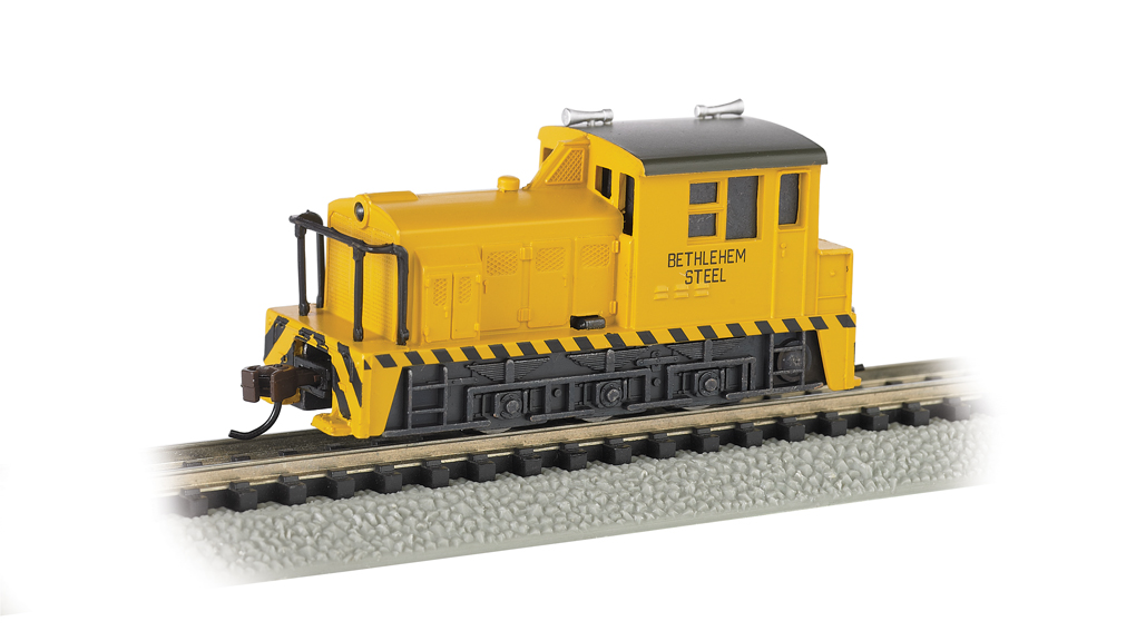
DC switch engine used in demo
Controlling DCC Train Engines
The same circuit setup with an H-bridge driver can be used for more advanced (and expensive) trains equipped with a Digital Command Control (DCC) encoder. It will require a bit more complex software to encode and send out the DCC commands that are used to set train speed and turn lights on and off.
Many higher end engines come equipped with DCC and they also tend to have a bit more detailed features. It will typically state "DCC" somewhere on the box, if the DCC decoder is installed in the engine. "DCC ready" means that it already has a connector plug to add a DCC decoder later. Many DC trains can be upgraded by adding a DCC encoder, if it will fit inside the engine case.

DCC decoder for engine with motor control and sound

DCC decoders used in model train engines contain a microcontroller with firmware
A complex series of bipolar (i.e., +/-) digital pulses both powers and sends commands to DCC trains. Typically the signal amplitude is around 16VAC. Both trains and accessories such as turnouts and lights get AC power (actually digital pulses and not sinusoidal) from the track and run it through a full wave rectifier circuit to generate DC to run the device. Many DCC devices need at least 15VDC from this circuit to operate correctly. Larger gauge trains may run near 22VDC. Each DCC engine can be assigned a unique address, so it is possible to run more than one train at a time. Most DCC equipped engines will also operate as a DC engine when DCC signals are not present and run off of DC track power from a DC controller.
DCC standards from NMRA describe the encoding of signals. In the DCC command seen below, the X axis line is OV, the pulse duration of a "1" bit is 58usec and a "0" is around 100usec (about twice as long). The error detection byte is the exclusive OR of the address and instruction data bytes. A train's address can be reprogrammed. Out of the box, they are typically set to address 3. The data byte contains speed settings. DCC commands need to be sent multiple times, since track noise could cause a data error (commands are checked using the error data byte and ignored in case of an error)

An example DCC command packet
Single DCC Engine Demo
Here is a very basic example that uses mbed to send a single DCC command and repeats it. It is controlling one train at address 3 turning on the headlight and moving the train back and forth along the track. The point here is to show that the hardware interface works, how the command packets are formed, the bit level encoding, and the timing using low-level C/C++ and mbed APIs. The H-bridge hardware setup is identical to the earlier example, but instead of PWMOut a DigitalOut bit is used with the required DCC packet standard time delays with wait_us().
#include "mbed.h"
//mbed DCC Model Train Demo

DigitalOut Track(p21); //Digital output bit used to drive track power via H-bridge

void DCC_send_command(unsigned int address, unsigned int inst, unsigned int repeat_count)
{
    unsigned __int64 command = 0x0000000000000000; // __int64 is the 64-bit integer type
    unsigned __int64 temp_command = 0x0000000000000000;
    unsigned __int64 prefix = 0x3FFF; // 14 "1" bits needed at start
    unsigned int error = 0x00; //error byte
    //calculate error detection byte with xor
    error = address ^ inst;
    //combine packet bits in basic DCC format
    command = (prefix<<28)|(address<<19)|(inst<<10)|((error)<<1)|0x01;
    //printf("\n\r %llx \n\r",command);
    int i=0;
//repeat DCC command lots of times
    while(i < repeat_count) {
        temp_command = command;
//loops through packet bits encoding and sending out digital pulses for a DCC command
        for (int j=0; j<64; j++) {
            if((temp_command&0x8000000000000000)==0) { //test packet bit
                //send data for a "0" bit
                Track=0;
                wait_us(100);
                Track=1;
                wait_us(100);
                //printf("0011");
            } else {
                //send data for a "1"bit
                Track=0;
                wait_us(58);
                Track=1;
                wait_us(58);
                //printf("01");
            }
            // next bit in packet
            temp_command = temp_command<<1;
        }
        i++;
    }
}
//DCC train demo turns on headlight, dims headlight, and moves back and forth at half speed forever
int main()
{
    //typical out of box default engine DCC address is 3 (at least for Bachmann trains)
    //Note: A DCC controller can reprogram the address whenever needed
    unsigned int DCCaddress = 0x03;
    //see http://www.nmra.org/standards/DCC/standards_rps/RP-921%202006%20Aug%2021.pdf
    //01DCSSSS for speed, D is direction (fwd=1 and rev=0), C is speed(SSSSC) LSB
    unsigned int DCCinst_forward = 0x68; //forward half speed
    unsigned int DCCinst_reverse = 0x48; //reverse half speed
    //100DDDDD for basic headlight functions
    unsigned int DCC_func_lighton = 0x90; //F0 turns on headlight function
    unsigned int DCC_func_dimlight = 0x91; //F0 + F1 dims headlight
    //
    //Basic DCC Demo Commands
    DCC_send_command(DCCaddress,DCC_func_lighton,200); // turn light on full
    DCC_send_command(DCCaddress,DCC_func_dimlight,200); //dim light
    DCC_send_command(DCCaddress,DCC_func_lighton,200);  //light full again
    while(1) {
        DCC_send_command(DCCaddress,DCCinst_forward,400); // forward half speed train address 3
        DCC_send_command(DCCaddress,DCCinst_reverse,400); // reverse half speed train address 3
    }
}
Video of Basic DCC single engine train demo
In the video above, a DCC equipped Bachmann Peter Witt street car is used with the default out of the box address 3 assignment. First a function command is sent with F0 to turn on the headlight. Then an F0+F1 command is sent which dims the headlight. It is followed by an F0 command which turns the headlight back to the full brightness level. While this is happening, the train is not moving.
Next in an infinite while loop, a command is sent repeatedly for about two seconds to move forward at half speed and then another command is sent to move in reverse for about two seconds at half speed. So the street car is seen moving slowly back and forth along the track.
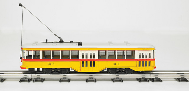
DCC Street Car used in video
Automatic Pickle Fork Demo with two DCC Train Engines
The waits used in the previous examples will become problematic once everything gets a bit more complex. Waits use processor time and power. They also make it more difficult to use the RTOS, monitor inputs, and schedule tasks. This example will eliminate the waits. First, the wait used to pulse a track switch (turnout) will be replaced using Timeout to setup an interrupt routine that turns off the circuit after a small time delay that is triggered by a hardware timer.
Encoded DCC command bits need to be sent out every 58-100 microseconds. These waits can be eliminated by using the SPI hardware to shift and send out bits. The mbed SPI SPI hardware can shift out up to 16-bits at a time without the processor. The SPI clock period is set to 58 microseconds. For an encoded 0 bit, sending out the pattern ”0011” will generate a 116 microsecond pulse width when the SPI hardware has a 58 microsecond clock period. For an encoded 1 bit, the pattern “01” is sent out. This is within the DCC specs for timing. Constantly changing the SPI or PWM clock rate on the fly might introduce other timing problems, so this approach was not used. To save time, a DCC command is encoded once and assembled into nine 16-bit packets stored in an array. This array of encoded bits is repeatedly sent out to the SPI hardware. In this demo, the only hardware change needed is to move the H-bridge control line from p21 to an SPI output pin (p5 is used in example code).
One of the advantages of DCC is that multiple trains can be controlled on a single track. In this demo, the Pickle fork layout will be used again, but this time it will have two DCC train engines. The two engines will move back and forth alternating track locations by controlling the track switch (turnout). The two DCC engines seen below are setup with a different address so that commands can be sent independently to each engine.
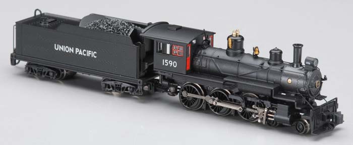
The Steam Engine is set to DCC address 3
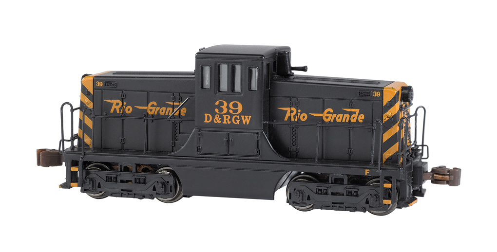
The Diesel Switch Engine is set to DCC address 2
#include "mbed.h"
//mbed DCC Model Train Demo using SPI

SPI Track(p5,p6,p7); //SPI output bit p5 is used to drive track power via H-bridge

DigitalOut Switch1(p22); // driver control output for one track switch solenoid coil
DigitalOut Switch2(p24); // driver control output for other track switch solenoid coil

Timeout PulseSwitch; //set up timer for track switch circuit pulse time delay

void DCC_send_command(unsigned int address, unsigned int inst, unsigned int repeat_count)
{
    unsigned __int64 command = 0x0000000000000000;
    unsigned __int64 temp_command = 0x0000000000000000;
    unsigned __int64 prefix = 0x3FFF; // 14 "1" prefix bits needed at start
    unsigned int error = 0x00; //error byte
    unsigned int DCC_encoded_buffer[9] = {0x5555,0x5553,0,0,0,0,0,0}; //preloads encoded prefix bits
    unsigned int DCC_encoded_bit_count = 32; //prefix bits already encoded
    //calculate error detection byte with xor
    error = address ^ inst;
    //combine packet bits in basic DCC format
    command = (prefix<<28)|(address<<19)|(inst<<10)|((error)<<1)|0x01;
    //printf("\n\r %llx",command);
    unsigned int k=0;
    temp_command = command<<37; //skips prefix bits - already encoded by initial array value
//encode DCC command into the DCC encoded bit array used for the nine  16-bit SPI transfers
//every 16-bts it needs to jump to the next array element (i.e. #bits/16 for array index)
    for (int i=0; i<27; i++) { //loop through rest of DCC command bits to encode them
        if ((temp_command & 0x8000000000000000) == 0) {
            // a O in the DCC command bit encodes to 0011 (a 0->1, but twice as long in SPI)
            DCC_encoded_buffer[DCC_encoded_bit_count/16] = DCC_encoded_buffer[DCC_encoded_bit_count/16] << 1;
            DCC_encoded_bit_count++; //add 0 bit
            DCC_encoded_buffer[DCC_encoded_bit_count/16] = DCC_encoded_buffer[DCC_encoded_bit_count/16] << 1;
            DCC_encoded_bit_count++; //add 0 bit
            DCC_encoded_buffer[DCC_encoded_bit_count/16] = DCC_encoded_buffer[DCC_encoded_bit_count/16] << 1;
            DCC_encoded_buffer[DCC_encoded_bit_count/16] = DCC_encoded_buffer[DCC_encoded_bit_count/16] | 1;
            DCC_encoded_bit_count++; //add 1 bit
            DCC_encoded_buffer[DCC_encoded_bit_count/16] = DCC_encoded_buffer[DCC_encoded_bit_count/16] << 1;
            DCC_encoded_buffer[DCC_encoded_bit_count/16] = DCC_encoded_buffer[DCC_encoded_bit_count/16] | 1;
            DCC_encoded_bit_count++; //add 1 bit
        } else
            // a 1 in the DCC command bit encodes to 01 (a 0->1)
        {
            DCC_encoded_buffer[DCC_encoded_bit_count/16] = DCC_encoded_buffer[DCC_encoded_bit_count/16] << 1;
            DCC_encoded_bit_count++; //add 0 bit
            DCC_encoded_buffer[DCC_encoded_bit_count/16] = DCC_encoded_buffer[DCC_encoded_bit_count/16] << 1;
            DCC_encoded_buffer[DCC_encoded_bit_count/16] = DCC_encoded_buffer[DCC_encoded_bit_count/16] | 1;
            DCC_encoded_bit_count++; //add 1 bit
        }
        temp_command = temp_command <<1;
    }
    //Fix last few bits - typically not a full 16-bits, so shift them left to MSB
    DCC_encoded_buffer[DCC_encoded_bit_count/16] = DCC_encoded_buffer[DCC_encoded_bit_count/16]<<(16-(DCC_encoded_bit_count % 16));

//repeat DCC command lots of times
    while(k <= repeat_count) {
//sending out encoded digital pulses for a DCC command 16 bits at a time using SPI hardware
        for (int j=0; j<9; j++) {
            Track.write(DCC_encoded_buffer[j]);
        }
        k++;
    }
}
//interrupt routine to turn both switch circuits off after time delay
void TrackSwitchOff()
{
    Switch1 = 0;
    Switch2 = 0;
}

void TrackSwitch(bool switchdir)
{
    Switch1 = 0;
    Switch2 = 0;
    if (switchdir == true)
        Switch1 = 1;
    else
        Switch2 = 1;
    PulseSwitch.attach(&TrackSwitchOff,0.5); //setup timer with int routine to turn off coil
}

//Demo for two DCC trains to swap locations on pickle fork automatically
int main()
{

    //typical out of box default engine DCC address is 3 (at least for Bachmann trains)
    //Note: A DCC controller can reprogram the address whenever needed
    unsigned int DCCaddress_Steam = 0x03;
    unsigned int DCCaddress_Diesel = 0x02;
    //see http://www.nmra.org/standards/DCC/standards_rps/RP-921%202006%20Aug%2021.pdf
    //01DCSSSS for speed, D is direction (fwd=1 and rev=0), C is speed(SSSSC) LSB
    unsigned int DCCinst_forward = 0x68; //forward half speed
    unsigned int DCCinst_reverse = 0x48; //reverse half speed
    unsigned int DCCinst_stop = 0x40; //stop
    //100DDDDD for basic headlight functions
    unsigned int DCC_func_lighton = 0x90; //F0 turns on headlight function
    unsigned int DCC_func_dimlight = 0x91; //F0 + F1 dims headlight
    const bool straight = true;
    const bool curved = false;
    //
    //Setup SPI hardware frequency and number of bits
    Track.frequency(1.0/0.000058); //DCC pulse time for a 1 bit - O is twice as long
    Track.format(16,3);
    //Turn off Switch Coil Circuits
    Switch1 = 0;
    Switch2 = 0;
    //Starts DCC Pickle Fork Demo Commands
    TrackSwitch(straight);
    // turn on headlights
    DCC_send_command(DCCaddress_Steam,DCC_func_dimlight,200); // dim light
    DCC_send_command(DCCaddress_Diesel,DCC_func_dimlight,200); //dim light
    DCC_send_command(DCCaddress_Steam,DCC_func_lighton,200);  //light on full
    DCC_send_command(DCCaddress_Diesel,DCC_func_lighton,200); //light on full
    // move trains back and forth on pickle fork switching tracks
    while(1) {
        // Pull out trains to single track from two track sidings
        DCC_send_command(DCCaddress_Steam,DCCinst_forward,625); // forward half speed train address 3
        DCC_send_command(DCCaddress_Steam,DCCinst_stop,50); // stop train address 3
        TrackSwitch(curved);
        DCC_send_command(DCCaddress_Diesel,DCCinst_forward,550); // forward half speed train address 2
        DCC_send_command(DCCaddress_Diesel,DCCinst_stop,50); // stop train address 2
        TrackSwitch(straight);
        // Back up trains into opposite track sidings
        DCC_send_command(DCCaddress_Diesel,DCCinst_reverse,450); // reverse half speed train address 2
        DCC_send_command(DCCaddress_Diesel,DCCinst_stop,50); // stop train address 2
        TrackSwitch(curved);
        DCC_send_command(DCCaddress_Steam,DCCinst_reverse,700); // forward half speed train address 3
        DCC_send_command(DCCaddress_Steam,DCCinst_stop,50); // stop train address 3
        //now switched track locations for two trains - switch them back again
        TrackSwitch(straight);
        // Pull out of sidings again
        DCC_send_command(DCCaddress_Diesel,DCCinst_forward,750); // forward half speed train address 2
        DCC_send_command(DCCaddress_Diesel,DCCinst_stop,50); // stop train address 2
        TrackSwitch(curved);
        DCC_send_command(DCCaddress_Steam,DCCinst_forward,500); // forward half speed train address 3
        DCC_send_command(DCCaddress_Steam,DCCinst_stop,50); // stop train address 3
        TrackSwitch(straight);
        // Back up Trains into opposite track sidings
        DCC_send_command(DCCaddress_Steam,DCCinst_reverse,500); // reverse half speed train address 3
        DCC_send_command(DCCaddress_Steam,DCCinst_stop,50); // stop train address 3
        TrackSwitch(curved);
        DCC_send_command(DCCaddress_Diesel,DCCinst_reverse,700); // reverse half speed train address 2
        DCC_send_command(DCCaddress_Diesel,DCCinst_stop,50); // stop train address 2
        TrackSwitch(straight);
    }
}
Video of Automatic Pickle Fork operation with two DCC engines
As seen in the video above, the two engines start out on a different track. They pull out into the single track area one at a time and then backup onto the opposite track. A click is heard each time one of the switch solenoid coil circuits is activated. The process repeats forever in a loop.
Further Enhancements for DCC
A C++ class for DCC control could be developed with more features. Currently some extra 0 bits are sent out between packets as all DCC packets are sent out at a fixed size.
For more complex layouts with more engines, and for mbed to have time for scheduling other events that might occur in automatic operation of complex train layouts, an interrupt driven approach to send DCC commands could be used. With mbed’s SPI hardware up to 16-bits could be handled in hardware to reduce the interrupt rate.
The example code sent only the basic DCC commands. There are more complex command formats that could be supported.
For multiple trains moving at the same time, DCC controllers typically repeat the last command to each address and constantly cycle through the different train addresses that have been sent a command. So a large buffer of DCC commands needs to be managed. When a new command appears that overrides an old command, the old command is deleted from the buffer and priority is given to send the new command first.
The DCC bit encoding insures that the average (DC) value of a pure DCC signal is zero. By adding a signal with a DC level between DCC commands, it is possible to independently control one DC engine with other DCC engines at the same time on the same track. Some commercial systems support this operation mode. This could be added to the example code by sending a second SPI bit pattern the majority of the time to control the speed and direction on the DC engine. In this second SPI bit pattern, the numbers of “1”s vs. “0”s would control the +/- DC levels. The DCC command refresh rate would be reduced a bit, but DCC engines keep running at the last speed command until a new command is sent, so this would not be an issue unless there were a large number of DCC engines being used. Some DC engines will overheat if they are not moving when used with DCC power for long periods of time.
There are some open source DCC projects available for command units and decoders. Unfortunately, most appear to contain some assembly language and other code that is processor specific for older less capable processors.
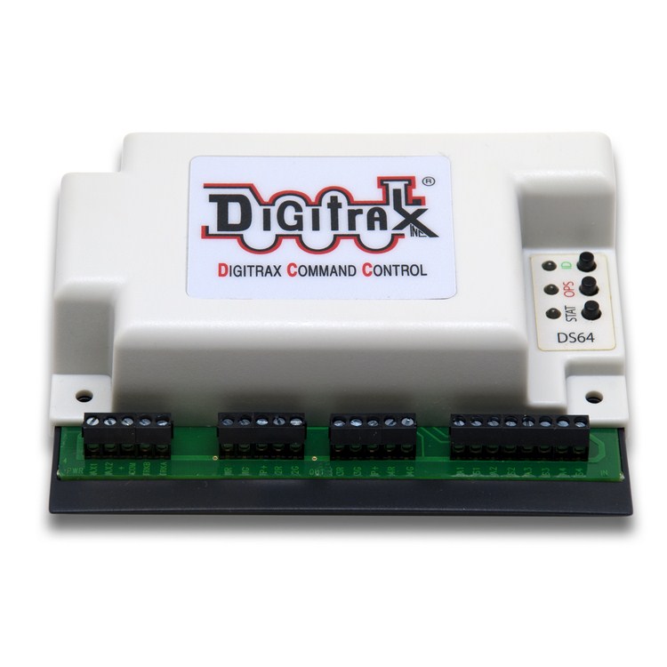
A DCC decoder with driver circuits for 4 track switches (not used inside engines).
Track Occupancy Sensors
To a point, dead reckoning (time and speed) can be used to determine the location of a train, but after awhile it will drift off since there is random wheel slippage and all motors will run at a slightly different speed in forward vs. reverse and at different temperatures and loads - unless the train always runs up against a track termination bumper and is forced to stop as in the earlier video demos. To automate a complex layout, some sensors will be needed to detect what portions of the track a train is on. These are called occupancy sensors. Sonar and IR sensors have been used for track occupancy sensors. In HO gauge and larger trains, magnets have been placed on the bottom of cars and detected by a reed switch or Hall effect sensor in the track, but this is more difficult in the smaller N and Z gauge trains. The wide beam width of SONAR sensors is likely problematic for small size trains.
IR LEDs with IR detectors are probably the most widely used approach in a small track layout. As seen in the drawings below, the IR signal from the LED reflects off of the bottom of train cars and hits the detector, or when used on the side the train interrupts the IR signal. In a permanent track layout, the IR sensor can be hidden in the track with leads running out of the bottom of the layout board. There is no easy commercially produced snap on occupancy detector solution for model trains. Some IR occupancy sensor kits are available, but they require custom installation in the train layout board and come with an interface PCB with a few parts that might not be needed, when using mbed on a breadboard.
Large layouts break the track up into different power blocks. It is possible to use a circuit that detects a train in a track's power block by detecting changes in current flow. Often this is done by sensing the voltage drop across a diode in series with track power. To ensure that cars and not just engines are detected, a resistor can be connected across two wheels on the car. Commercial occupancy detectors are also available that use this approach. 

Azatrax's IR detector kit sensor setups are shown above
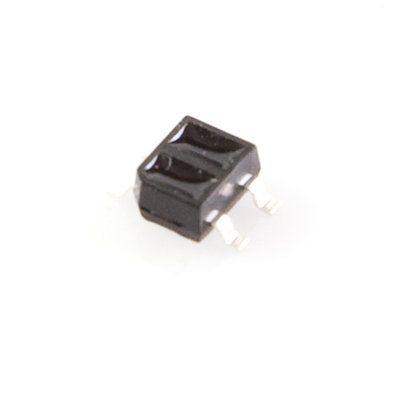
SMD IR reflectance sensor module
There are also some small IR reflectance sensor modules such as the QRE1113 used in line following robots such as the m3pi that could be hidden a bit easier than a discrete LED and phototransistor in small gauge train tracks. These could be hooked up to an mbed analog input.
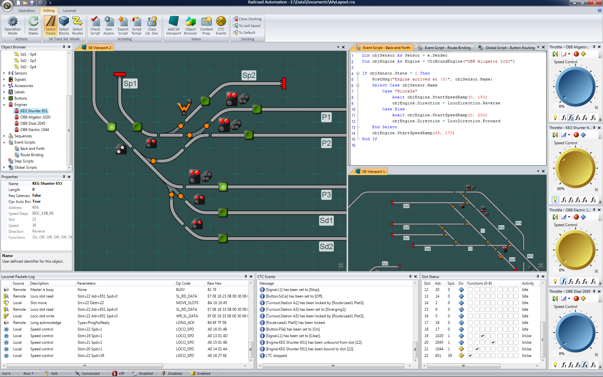
There are even free and commercial software products to control and fully automate large layouts.
Adding Sound
Small sound PCBs are available that can be mounted inside engines and draw power off of the track. There are also high-end DCC decoders with built-in sound features. Sounds can be controlled using other DCC function commands similar to the headlight functions in the earlier examples. In N and Z gauge, space is too limited in most cases. N gauge DCC engines with sound are just starting to appear. Using mbed, train sounds could be added using the waveplayer code with a speaker and small audio amp or PC speaker set using audio files stored on an uSD card or short audio clips can be played using flash memory.
Video of a DCC model train with sound
Sounds adds quite a bit to a model train. In the video above, note that the sound effect is tied in with the DCC throttle setting. Most systems have several engine sound samples that are programmed in the the sound device which often contains a DSP chip.
Adding Lighting
Many train engines come equipped with internal lights. Some even have front and rear lights that activate based on the direction the engine is moving. DCC engines with lighting have a special DCC command to turn the lights on and off and even dim the lights. LED lighting is the way to go to add more lights for signals and buildings on a layout.
mbed used to control RR crossing signals
In the video above, mbed was used to flash RR crossing signals for a model train. There are even tiny LEDs available with a tiny full wave bridge rectifier and dropping resistor already attached with wire leads for use directly on track or auxiliary 16V AC power. One such device is seen below. LEDs are even available with built in lighting effects such as blinking slow or fast, fire, and arc welding.
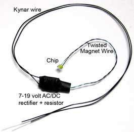
SMD LED already setup for track AC power use with wire leads
For several code examples using mbed for LED lighting and sound effects see LED lighting and sound effects for modelers and miniaturists.
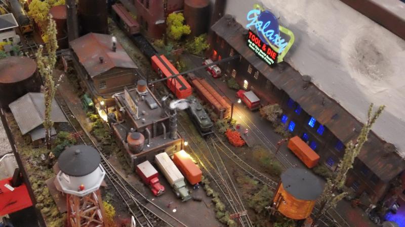
A complex track layout with LED lighting
Layouts can be quite detailed as you can see in the photo above and video below. A wide array of products and kits for scenic details and buildings are available. Instructional videos are available that show how they can be built. Free and commercial CAD tools are also available to help design track layouts.
A Highly Detailed N Gauge Layout Built on a Door
Using Commercial DCC controllers for IoT train control
Most commercial DCC controllers use a hand held throttle device to control trains. It is difficult to control more than two trains at the same time, so they typically have two active throttle controls.
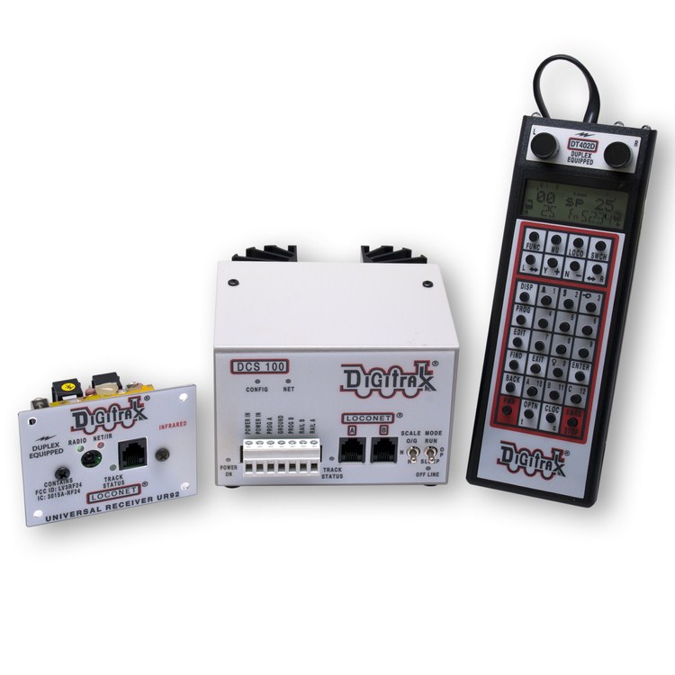
Digitrax DCC controller and handheld throttle
Wi-Fi Throttle
Many DCC control units also support some type of a PC serial interface. There is free public domain PC software, JMRI, to control DCC trains using this interface with a GUI on the PC. JMRI also features a web server that can be used to control the throttle from an iOS, Android device or web page making the train an IoT device. Mbed could also be used to send serial throttle commands to a commercial DCC control unit and utilize its power supply, driver circuit, and DCC command buffers or with a Wi Fi interface it could be used to build a remote throttle.
Android IoT Train Control with JMRI and a commercial DCC control unit.
Bluetooth
Recently, a few engines and starter train sets have been introduced with internal Bluetooth control modules in the engine's decoder. An App is downloaded to a smartphone or tablet to control the engine directly using the Bluetooth RF link. An mbed with the appropriate Bluetooth module and software could connect to the engine and control the train.
Micro Train's Model Train Factory Tour
2 comments on Controlling a Model Railroad using mbed:
Please log in to post comments.

Jim:
Please be advised I am just curious, and do not really know anything about model railroading, but I was at a model railroad presentation at the Seattle Science Center on Saturday and the technology is interesting.
Look's like the voltage for the 'N' track motors is 0-12V. I looked at the waveforms on the open DDC website are 30V PWM'd at 50% to obtain 15volts.
http://www.opendcc.de/index.html
When I look at suggested power supplies on other sites, they spec 12Volt linear (LM317) power supplies, and then PWM them.
I realize that you could PWM a 15v raw supply to output 12v, but would it not be more efficient if you limited the PWM to less than 50% and when down from there? And if the raw voltage were 30V pk -pk with 15v above and 15v below would not this make polarity reversal much more easier?
Again, I really do not know what I am talking about in your world. Just wondering, and would really like to know more.
Marc
seattle