An Introduction to RC Servos
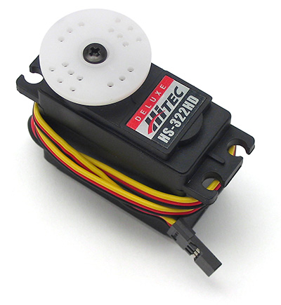
An RC Servo
A typical radio control (RC) servo is shown above. Servos have a drive wheel (white in image above) that is controlled by a PWM coded signal. The wheel moves around 90-180 degrees in normal operation. Radio control servomotors are mass-produced for the hobby market and are therefore relatively inexpensive and consistently available. They are ideally suited for many small low-cost hobbyist and student robotics applications.
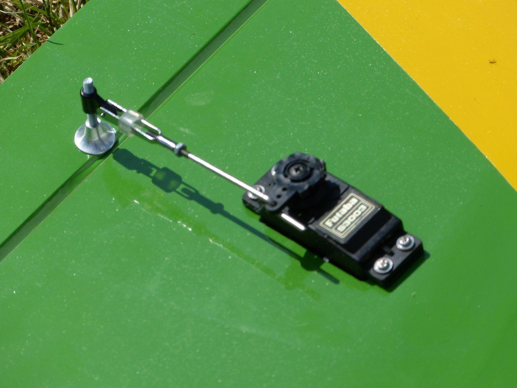
This RC servo is mounted under the RC airplane's wing and moves a wire push rod to control the aileron
The wheel or control horn on the servo can be attached to a stiff wire push rod to move mechanical parts such as an airplane control surface as seen above, it can be attached to other parts or sensors to rotate them, or even a drive wheel can be attached to move a robot. A humanoid robot uses a servo to move each joint and can contain over twenty servos.
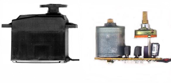
A Standard Hobbyist RC servo, and on the left with case and gears removed to show electronics
Internally, the servo contains a DC drive motor (seen on the left in figure above), a built-in driver, control circuitry, and a gear reduction system. The tall electronic component on the right is a potentiometer that is used to sense and control the position of the servo's output shaft.The servo shown is a Futaba S3003. They are all almost identical, internally in standard low-cost servos. They are small, produce a relatively large amount of torque for their size, and run at the appropriate speed for a robotics drive motor.
A servo code example for mbed is available in the cookbook that uses mbed's hardware PWM outputs.
Hello World!
Library
Import library
Public Member Functions |
|
| Servo (PinName pin) | |
|
Create a servo object connected to the specified PwmOut pin.
|
|
| void | write (float percent) |
|
Set the servo position, normalised to it's full range.
|
|
| float | read () |
|
Read the servo motors current position.
|
|
| void | position (float degrees) |
|
Set the servo position.
|
|
| void | calibrate (float range=0.0005, float degrees=45.0) |
|
Allows calibration of the range and angles for a particular servo.
|
|
| Servo & | operator= (float percent) |
|
Shorthand for the write and read functions.
|
|
This library controls a standard R/C model servo using a PwmOut signal, and provides control of the servo between min and max by setting it to 0.0 - 1.0.
Warning
A servo requires higher current than the USB port can safely provide, and so it is essential that you power the servo using an external supply, such as a 4xAA (6v) battery pack or an appropriate DC power adaptor.
Most servos will require an external power supply or battery when used with mbed. All but the smallest micro ones draw more current than is available over the USB cable (<250ma for the servo assuming the mbed draws around 200ma). Don't forget to only connect the grounds together when using multiple power supplies.
A servo has three wires, +4.8 to +6 Volt DC power, ground, and the PWM signal wire. Some new Digital servos can operate at up to 7.4V. The assignment of the pins for the three signals on the connector varies among different servo manufacturers. For Futaba servos, the red wire is +5, black is ground, and the white or yellow wire is the pulse width signal line. For JR and Hitec servos, the orange or yellow wire is the signal line and red is +5, and black or brown is ground. Servo cables have the same .1 inch spacing as a breadboard. An extra long 3-pin header can be used to plug it into a breadboard or jumper wires can be pushed into the connector. If the servo cable needs to be longer off-the-shelf servo extension cables are also available.
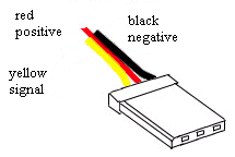
Hitec Servo Cable
Wiring for servo demo code
| mbed | servo | external DC supply |
|---|---|---|
| gnd | gnd (black) | gnd |
| power (red) | +4.8V to 6V | |
| p21 or any PWM | PWM signal input (white, yellow, orange) |
The control circuitry of the servo uses a potentiometer (variable resistor) that is used to sense the angular position of the output shaft. The potentiometer is the tall component on the right in the figure above. The output shaft of a servo normally travels 180-210 degrees.

PWM signal used to control an RC Servo
A single PWM control bit is used to specify the angular position of the shaft. The timing of this bit specifies the angular position for the shaft. The potentiometer senses the angle, and if the shaft is not at the correct angle, the internal control circuit turns the motor in the correct direction until the desired angle is sensed.
The control signal bit specifies the desired angle. The desired angle is encoded using pulse width modulation (PWM). The width of the active high pulse varies from 1-2 ms. A 1ms pulse is 0 degrees, 1.5ms is 90 degrees and a 2 ms pulse is approximately 180 degrees. New timing pulses are sent to the servo every 20 ms.

RC servos are available in several standard sizes
Small RC servos gear down the DC motor quite a bit and have a surprising amount of torque for their size. Servos come in several different sizes. In general, the larger and more expensive servos have more torque. Some automobiles even use servo motors to move air dampers in the heating, cooling and exhaust systems. There are also some linear servos that move a rod back and forth, but these are not as common as servos that rotate.
Most low-cost servos come with plastic gears that can wear out with extensive use. Servos with metal gears and ball bearings are more durable, but also more expensive. Replacement parts and upgrade kits are available for the more common servos.
Using a large number of servos
If a large number of servos are needed and mbed does not have enough PWM outputs, the TI TLC5940 is a 16 channel driver IC with 12 bit duty cycle PWM control (0 - 4095), 6 bit current limit control (0 - 63), and a daisy chainable serial interface (SPI). Maximum drive current is 120 MA per output. It is handy for expanding the number of high current drive PWM outputs available. This IC was originally targeted for driving LED arrays. 16 PWM outputs might sound like a lot, but a humanoid robot might need over twenty to control all of the servo motors used the joints. This IC comes in a DIP package. Sparkfun also has a breakout board for the surface mount version and a code example is available in the mbed cookbook. PWM signals can also be generated on any digital output pin using software timing.
Another common IC used for driving up to 16 servos is the PCA9685. This chip is used on the Pi hat 16 servo control board seen below from Sparkfun. It uses an I2C interface and servo cables plug directly into header pins on the board.
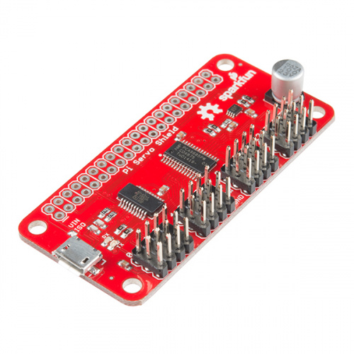
This board from Sparkfun controls up to 16 servos using I2C.
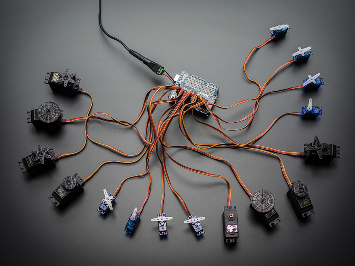
Adafruit has a couple of similar boards that can control 16 servos.
Modifying Servos to make Robot Drive Motors
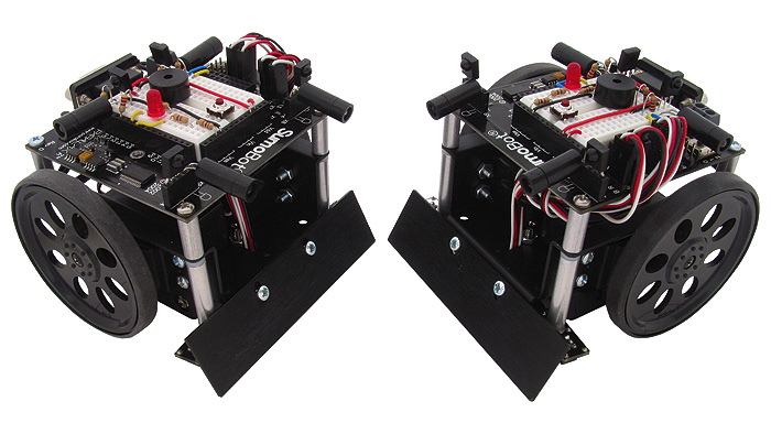
These small sumobot robots use modified servos to drive the wheels
In many robots with two drive wheels, a motor is needed that rotates continuously and is reversible. Normally, a servo has a mechanical stop that prevents it from traveling move than half a revolution. If this stop is removed along with other modifications to the potentiometer, a servo can be converted to a continuously rotating drive motor. The servo then functions as a geared DC motor with a built-in driver and control circuit. Modifications to the servo are not reversible and they will void the warranty. This has become such a common practice for robots that some robot kit vendors now sell "continuous rotation" servos that are already modified and even wheels with tires that attach to the servos output shaft
To modify the servo, open the housing by removing the screws and carefully note the location of the gears, so that they can be reassembled later. The potentiometer can be replaced with two 2.2K ohm ¼ watt resistors or disconnected by cutting the potentiometer shaft shorter and setting it to the center position so that it reports the 90-degree position. A more accurate setting can be achieved by sending the servo a 1.5ms pulse and adjusting the potentiometer until the motor stops moving. The potentiometer can then be glued in place with CA glue. In the center position the potentiometer will have the same resistance from each of the outside pins to the center pin. If the potentiometer is replaced with two resistors, a resistor is connected between each of the two outside pins and the center pin. In some servos, there will be less mechanical play if the potentiometer is disabled by cutting the center pin and modified by drilling out the stop on the potentiometer so that it can rotate freely. The two resistors are then added to replace the potentiometer in the circuit.
The largest gear in the gear train that drives the output shaft normally has a tab molded on it that serves as the mechanical stop. After removing the screw on the output shaft and removing the large gear, the mechanical stop can be carefully trimmed off with a hobby saw, knife, or small rotary-grinding tool. The servo is then carefully re-assembled. After modifications, if a pulse shorter than 1.5 ms is sent, the motor will continuously rotate in one direction. If a pulse longer than 1.5 ms is sent the motor will continuously rotate in the other direction. The 1.5 ms or 90-degree position is sometimes called the neutral position or dead zone. The drive signal to the motor is proportional, so the farther it is from the neutral position the faster it moves. This can be used to control the speed of the motor if the neutral position is carefully adjusted. A pulse width of 0 ms or no pulse will stop the servomotor. The modifications to the potentiometer circuit eliminate the servo's positional feedback, but add on optical encoder kits are also available for modified RC servos to provide motion feedback for more advanced control of servos modified for continuous rotation.
Modifying a servo for continuous rotation
Digital Servos
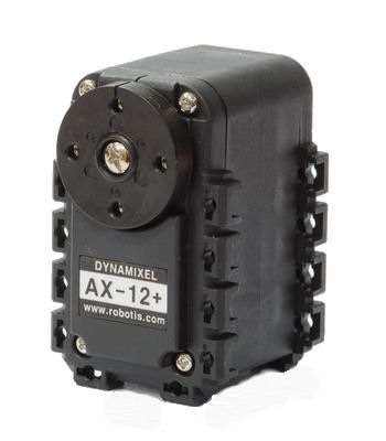
Dynamixel AX-12 Digital Servo
Digital servos add a microcontroller that accepts serial commands to set limits and control the servo. Typically, they also have a faster internal sampling rate which provides faster response times with the same motor. The only disadvantage is the higher cost than the traditional analog servos using PWM signals. Some Digital servos default to analog mode with the same PWM signal as the non-digital servos. Many digital servos can also be chained together using one serial command wire. Since a humanoid robot can have over twenty servos, this feature can greatly simplify wiring and reduce the number of PWM output pins needed. I/O expander chips are available with PWM output pins, if more PWM outputs are needed. Two code examples using Digital servos are currently available in the cookbook.
Off-the-Shelf Hardware for Servos
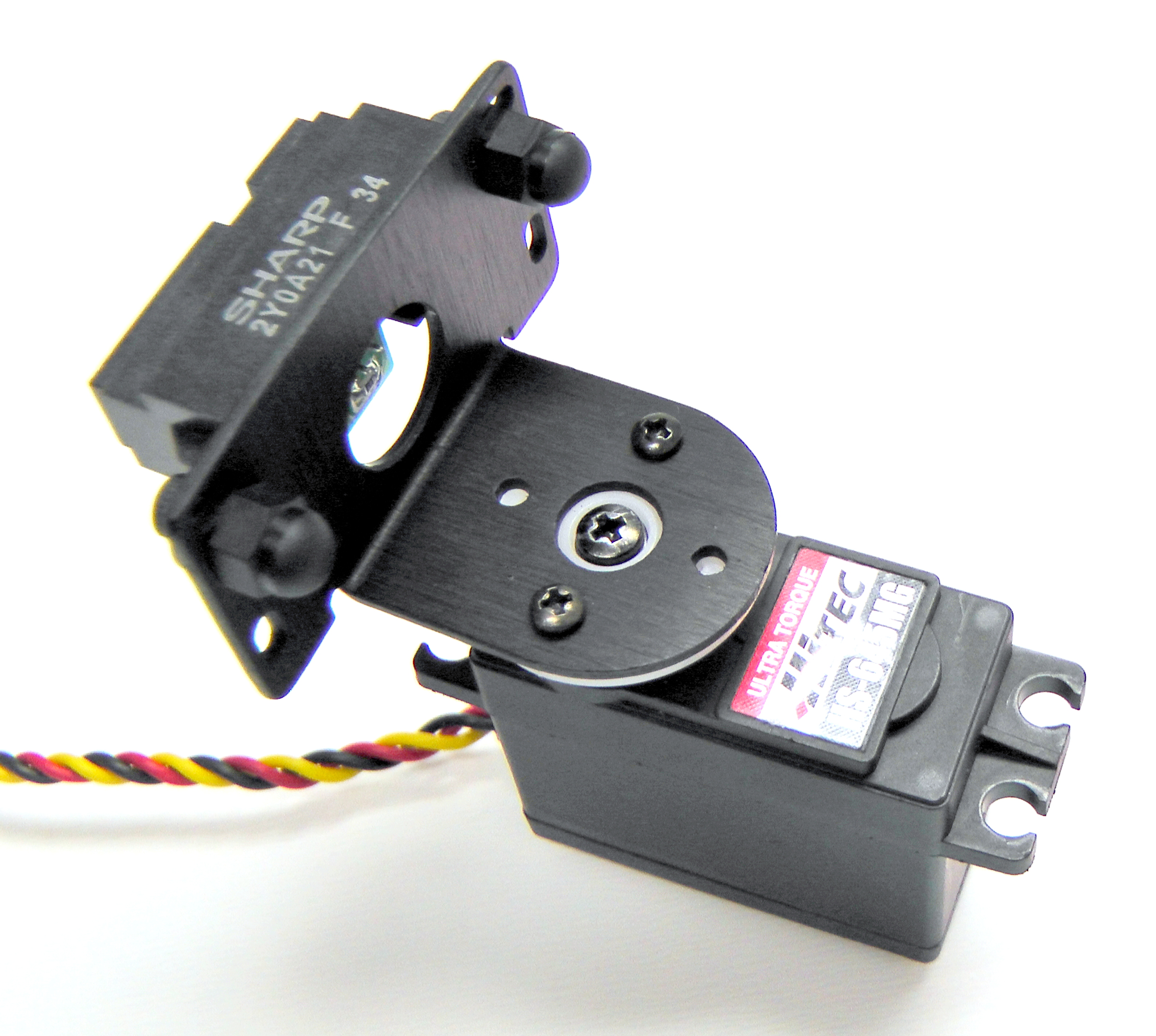
This bracket rotates an IR distance or Sonar sensor using a servo
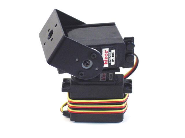
This pan and tilt bracket uses two servos and is handy to point cameras or sensors in any direction
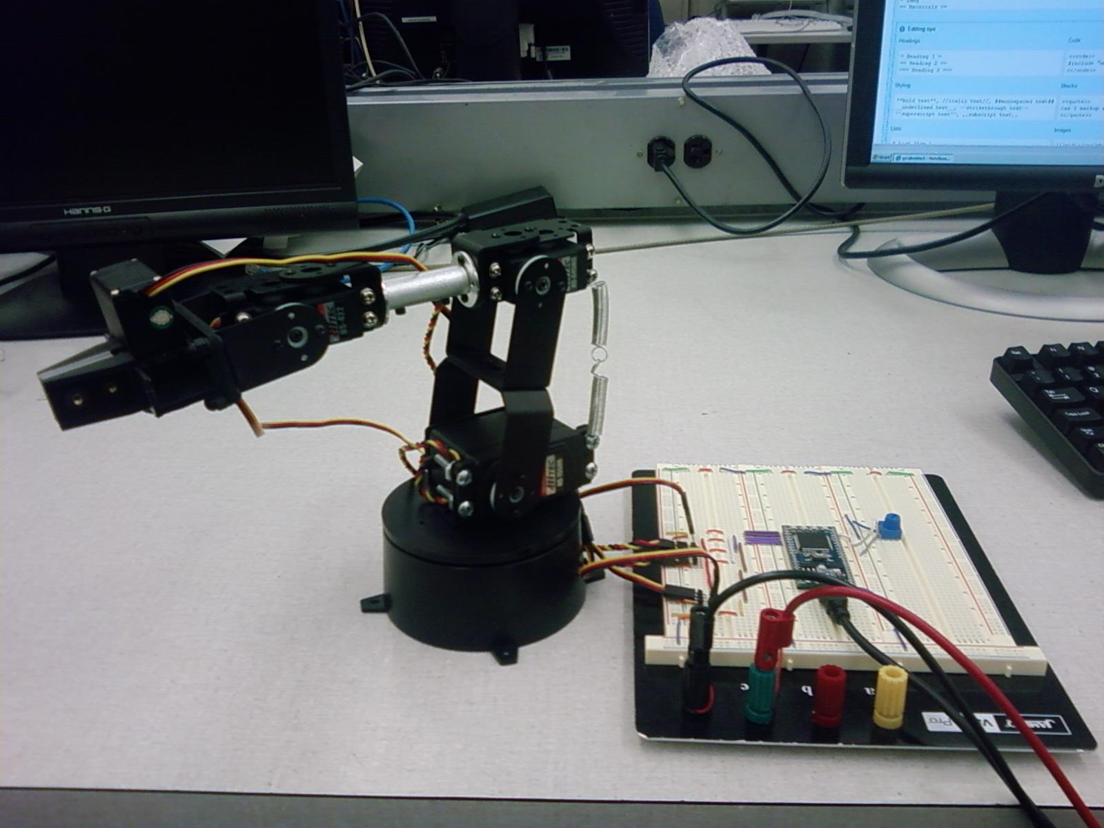
This robot arm has five servos (one per joint) controlled by the mbed's PWM outputs
Several companies make special hardware just for mounting and connecting RC servos. Lynxmotion makes a servo erector kit with a huge assortment of hardware and mounting brackets to build complex devices and robots with servos. A large kit is available or individual parts can be purchased as needed for a project. Servocity also has a vast array of servos and hardware for servos.
Devices built using servos and the servo erector kit's aluminum and lexan parts
Videos of Different Types of Robots Built Using RC Servos
Here are some interesting videos showing the wide range of robotics projects that can be built using servos.
Introduction to using servos on RC aircraft
A popular sumobot kit that uses continuous rotation servos for drive wheels.
A low cost robot arm built with servos
A Hexapod buglike robot with servos
A robot snake with servos
Humanoid robots with servos
Can transformer robot using mbed for control of six servos
A self-balancing robot using two continuous rotation servos with accelerometer and gyro sensors for control system feedback.
Industrial Servo Motors
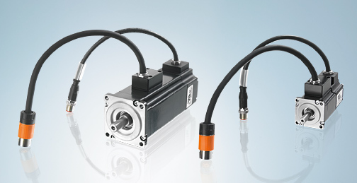
Industrial Servo Motors
Industrial servo motors are similar to RC servos in that they contain a motor with a position feedback control loop. They are larger, more powerful, more durable, and more expensive. They can be built using stepper motors or DC motors with a rotary encoder such as an optical shaft encoder. They are used in larger industrial robots and industrial automation systems.
Assembly of a Large Industrial Robot Arm
This Kinetic Sculpture in the Singapore Airport uses 1,216 Industrial Servos
Please log in to post comments.
