Important changes to repositories hosted on mbed.com
Mbed hosted mercurial repositories are deprecated and are due to be permanently deleted in July 2026.
To keep a copy of this software download the repository Zip archive or clone locally using Mercurial.
It is also possible to export all your personal repositories from the account settings page.
Dependencies: UniGraphic mbed
Car Diagnostics with CAN Communication
Device Description
Using CAN communication protocol we sought to connect to a vehicle's computing unit in which we would obtain real time data that would be displayed on an LCD screen. A mbed LPC1768 micro controller was used for this project.
Hardware
ARM microcontroller (mbed LPC1768), IC Transceiver CAN (MCP2551), DB9 breadboard adapter , OBDII cable, LCD display/resistive touch 2.4” 240x320 (DM-TFT24-104), 220 Ohm resistors (x 2)

Software
Five files in the project: globals.h, globals.cpp, OBDII.h, OBDII.cpp, and main.cpp. The main.cpp just serves to call the functions in the rest of the files, and only features a few lines of code. The global files are used just for making the CANMessage and CAN output, as well as a few other miscellaneous items. The OBDII files are where most of the magic happens, this is where the PID codes are defined, as well as the majority of the code, which still is much. The reading, writing, and decoding of the CAN information is all done in these OBDII files.
Program Flow

Key Functions
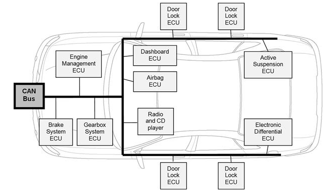
We don't actually have many functions in the program, which in turn means that the functions that we do have are very important. First and foremost, the set_frequency function enables us to talk with the different ECU's in the car based on their frequency. The majority of our PID requests were requesting information from the Engine Management ECU which operates at a frequency of 500 kbps. Other frequencies include, 125 and 250 kbps. The other key function is the request function. It takes in a PID char byte that is then sent to the Car and used to ask for specific information and to make sure that the information that we receive back is valid. Once we are able to read the data that comes back, we then determine what type of data is sent and compare it to what we were expecting. Depending on the PID and data received various equations are done to return the desired information.
Background on New Methods
CAN communication
When using a CAN communication, the devices on the CAN-Bus send data through the network in packets called frames. Any device on the bus can transmit data at anyone since its a peer to peer communication network. With any device being able to transmit it requires that there is a priority level with each ECU's transmission. Taking a deeper look at each frame that an ECU sends, it begins with a Start of frame bit which is followed by a 11 or 29 bit arbitration identification bit. The arbitration ID indicates the messages priority and allows for ECU's to decided whether it applies to them or not. A Data length bit is then sent which indicates the number of data bits that will be transfer. Following the data length the 0-8 bit data bits are then transmitted. CAN also has an error checking method through its cyclic redundancy check. The frame also includes an acknowledgement bit that is sent between the communicating ECU's in order to confirm a complete message between the two. Once the acknowledgment has been complete the frame is closed through end of frame bit. So CAN communication protocol is an effective for many applications that can deal with the electromagnetic interference of the surrounding environment.
CAN communication network in automotive vehicles:
