Playing MP3 with Music Shield and WIZwiki-W7500
Dependencies: FTPClient javakysSDFileSystem2 WIZnetInterface mbed
You are viewing an older revision! See the latest version
Homepage
Prerequisite
This example is for playing MP3 file stored in SD card on WIZwiki-W7500 and updating MP3 files from server to SD card via FTP protocol.
To implement this function, you need a Platform board, network Interface board, MP3 decoder board and SD card. Below are what we used.
- WIZwiki-W7500 from WIZnet (Platform board and Ethernet I/F board)
- Music shield from Seeed Studio
- SD card
Hardware Configuration
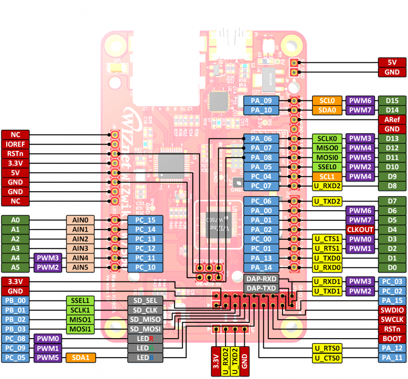
WIZwiki-W7500 Pin map

SPI1 for SD Card
SPI1 on WIZwiki-W7100 is for reading from or writing to SD card and pins for SPI1 are PB_0, PB_1, PB_2 and PB_3.
SPI0 and other control pins for MP3 decoder
WIZwiki-W7500 communicates to MP3 decoder on Music Shield via SPI0 pins of which consists of PC_12, D11, D12 and D13.
And PC_13, PC_14 and PC-15 are used for DCS, DREQ and RST, respectively.
InterruptIn pins for 5-Way Navigation Switch
D3, D4, D5, D6 and D7 are connected to 5 way navigation switch on Music Shield.
When user pushes the switch to one way, a relevant pin is grounded so that he or she should make it set high at the beginning.
Software
SPI Initialization
//Declaration in VS1002.cpp
VS1002::VS1002(PinName mmosi, PinName mmiso, PinName ssck, PinName ccs, const char *name, PinName mosi, PinName miso, PinName sck, PinName cs, PinName rst, PinName dreq, PinName dcs)
    : _DREQ(dreq), _RST(rst), _spi(mosi, miso, sck), _CS(cs), _DCS(dcs), _sd(mmosi, mmiso, ssck, ccs, name) {

    }

//Initialization in main.cpp
VS1002 mp3(PB_3, PB_2, PB_1, PB_0,"sdc",D11, D12 ,D13, PC_12, PC_15, PC_14, PC_13);
Mapping 5-Way Navigation Switch into InterruptIn pins
main.cpp
InterruptIn K_VU(D3); // Volume UP Key
InterruptIn K_VD(D7); // Volume Down Key
InterruptIn K_FW(D4); // Foward Key
InterruptIn K_BW(D6); // Backward Key
InterruptIn K_ONOFF(D5); //Play/Resume or Pause Key
Additional codes due to mbed library bug of WIZwiki-W7500
main.cpp
//Operating Clock Frequency Set
*(volatile uint32_t *)(0x41001014) = 0x0060100;

//Set all InterruptIn pins to Internal PullUp
*(volatile uint32_t *)(0x41003000) = 0x00000002; //D6
*(volatile uint32_t *)(0x41003004) = 0x00000002; //D5
*(volatile uint32_t *)(0x41003008) = 0x00000002;  //D4
*(volatile uint32_t *)(0x41003080) = 0x00000002;  //D3
*(volatile uint32_t *)(0x41003098) = 0x00000002;  //D7