Pulse Width Modulation
All exercises in this topic will be carried out using an mbed application board. mbed uses pins p21 to p26 for use with a PwmOut class. On mbed application board pins p21 and p22 are connected to a servo motor headers, pins p23, p24 and p25 are connected to a RGB LED, and p26 is connected to a speaker.
Generating PWM signals
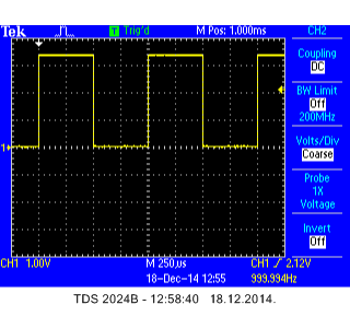
Create a PWM signal which can be seen on an oscilloscope. Set the frequency of the PWM signal to 1 kHz. Set the initial duty cycle to 50%. Check if the signal is generated correctly.
A possible solution is given below.
Import programMAB_PWM_Oscilloscope_1
A simple 1 kHz PWM signal generator with 50% duty cycle.
An oscillogram is shown in the following figure:

Now modify the above program in a way that duty cycle changes with the setting of a potentiometer Pot1 or by entering a value over a terminal. In the modified program use the following member functions explicitly: write(), pulsewidth(), pulsewidth_ms() and pulsewidth_us(), to get acquainted with most important member functions of PwmOut class.
A possible solution is given below.
Import programMAB_PWM_Oscilloscope_2
A simple 1 kHz PWM signal generator with adjustable duty cycle over potentiometer.
Run the program and observe how the duty cycle changes with turning of Pot1 or by typing on terminal.
Controlling LED brightness with PWM
Create a program that controls a brightness of mbed onboard LED1 using PWM. The brightness must be set by using potentiometer Pot2.
A possible solution is given in the program below.
Import programMAB_PWM_LED1
A simple program that controls the LED1 brightness by using potentiometer.
Controlling RGB LED color with PWM
A RGB LED consists basically of 3 separate LEDs (red, green and blue). By mixing these basic three colors, it is possible to generate all other colors from a visible spectrum. If you take a look at the schematics on the sheet 2, section B1 and B2, you will notice that all 3 LEDs are connected in common anode mode. Therefore, the outputs should be configured as open drain! Since this is not possible in the PwmOut class, the power supply to the common anode of the LEDs must be 3.3 V (which it is!) for everything to work fine. SInce this basically is the open drain configuration, the logic will be inverse, meaning that 100% duty cycle will turn off the LED, and 0% duty cycle will turn on the LED with full brightness.
Create the program that sets the red color by Pot1, the green color by Pot2 and blue color by pressing the center joystick key (p14).
A possible solution is given in the program below.
Import programMAB_PWM_RGB_LED
A simple program to control the color of RGB LED.
Outputting to a speaker
Write a program that will play a Ciciban song on a speaker. The song beat must be adjustable over potentiometer Pot1, and song scales must be adjustable over potentiometer Pot2.
The solution is given in a program below. Be creative, but do not too much creative in the lab :)
Import programMAB_PWM_Speaker
A program for playing Ciciban song. All notes are included, so any song can be easily added if you know its notes.
Control of servo motor position
Write the program that will control the position of servo motor SG90 Micro Servo via a potentiometer setting. Study the motor datasheet and carefully connect the motor on the 5 V laboratory power supply source. Write a program that uses full scales of motor angle position and full turn of the potentiometer (linear scaling).
Congratulations!
You have completed all the exercises in the Pulse width modulation topic.
Return to TVZ Mechatronics Team Homepage.
