Examples of GPIO usage
Optical sensors
You have a transmissive and reflective optical sensors at your disposal.
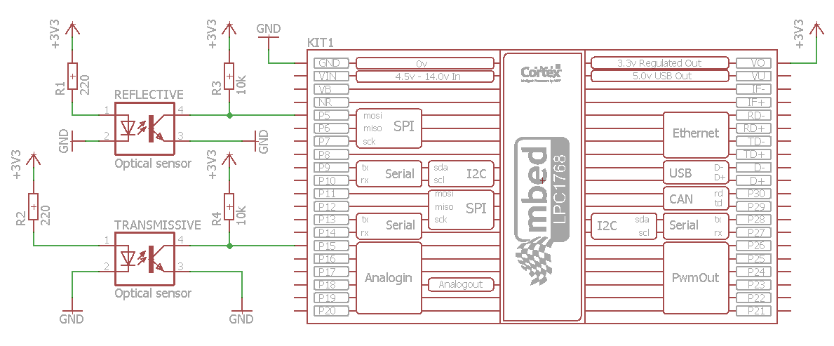
Connect the components on the breadboard according to the following schematics:

Write the program that will turn mbed's LEDs (LED1 and LED2) on/off based on the states of transmissive and reflective optical sensors.
Note
Pin numbers of optical sensors on this schematics do not match pin numbers of available optical sensors. Use datasheets' information for connecting sensors.
Driving an opto isolated relay
You have a 1-channel relay module at your disposal, shown on the following figure:

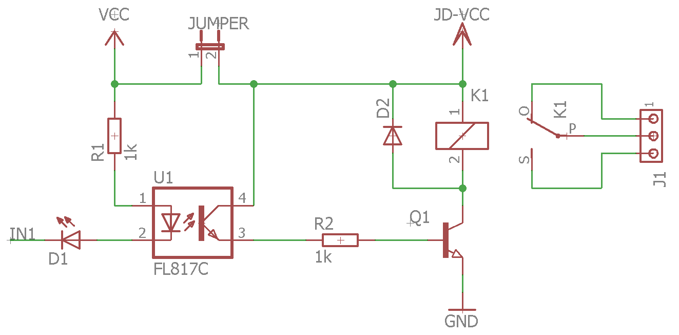
Electrical schematics of one channel is given on the following figure:

Examine the schematics closely. What is the role of D2 diode?
Connect the relay module with mbed LPC1768 using the USB 5 V supply voltage for a relay coil. If you want to achieve full isolation of mbed voltage supply and relay coil supply, it is necessary to remove the jumper that connects JD-VCC and VCC, and connect separate 5 V power supplies on those pins.
Write a program that will turn the relay on/off using the sliding switch (SPDT) or based on the state of the optical sensor. Draw a schematics of how you connected your mbed with the relay module and the switch. Did you configure your digital output as push-pull or open-drain?
Congratulations!
You have completed all the exercises in the Examples of GPIO usage topic.
Return to TVZ Mechatronics Team Homepage.