You are viewing an older revision! See the latest version
Digital inputs and outputs
Exercise 1: mbed Hello World
Follow instructions on /handbook/Creating-a-program.
Modify the program to flash other 3 LEDs.
Exercise 2: Using external LEDs
You will be using two schematics in this exercise to compare two different digital output modes. Digital input modes will also be compared in the next exercise.
Note
You will need two LEDs, two 330 or 220 Ohm resistors, mechanical switch, some wires, breadboard and of course mbed board to complete this exercise.
Standard digital outputs
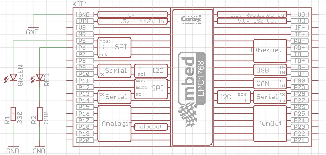
Connect the components on the breadboard according to the following schematics:

Examine the following code:
#include "mbed.h"

DigitalOut green(p5);
DigitalOut red(p6);

int main() {
    while(1) {
        green = 1;
        red = 0;
        wait(0.5);
        green = 0;
        red = 1;
        wait(0.2);
    }
}
Notice that digital output pins (p5 and p6) are declared using DigitalOut class, which does not (yet) provide the option for setting the output mode. The default mode used in this case is standard (conventional) mode, which drives the output pin from internal power supply.
Digital outputs in open drain mode
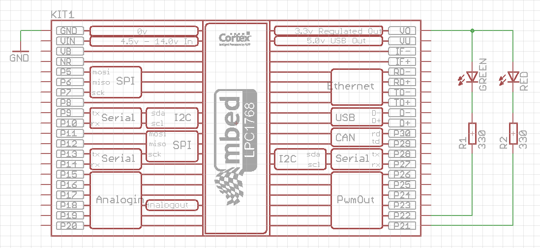
Connect the components on the breadboard according to the following schematics:

Examine the following code:
#include "mbed.h"

DigitalInOut green(p22, PIN_OUTPUT, OpenDrain, 1); // The first way of digital output configuration
DigitalInOut red(p21); // The second way of digital output configuration

int main() {
    red.output(); // Addition 1 for the second way of digital output configuration
    red.mode(OpenDrain);  // Addition 2 for the second way of digital output configuration
    red = 1; // Turn red LED off (inverse logic)
    while(1) {
        green = 1;
        red = 0;
        wait(0.5);
        green = 0;
        red = 1;
        wait(0.2);
    }
}
In this way the digital output pins are configured as open drain outputs. A class used for this purpose is DigitalInOut, since the standard class DigitalOut does not (yet) have the option for open drain mode. DigitalInOut class has two constructors, and both of them are used and commented in the example code above.
You may also notice the inverse logic of this configuration. When the output is set to logic 1 state, a potential of that pin is 3.3 V, so the potential difference (voltage) accros the LED and resistor is zero and LED is off. When the output is set to logic 0, the potential of that pin drops to 0 V, and voltage across the LED and resistor becomes 3.3 V and LED turns on.
Be careful!
If you connect the LEDs in the open drain mode (the second schematics) and you do not configure the outputs to be in the open drain mode, the LEDs will probably flash fine, but there is a high risk of damaging the mbed input circuitry! The open drain mode is sometimes the only way of driving your digital output (e.g. 7-segment display with common anode), so use it properly when necessary.
Exercise 3: Digital input
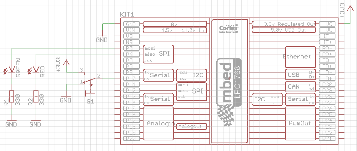
Add a single-pole double-throw switch to the first schematics with LEDs, as shown in the following figure:

Examine the following code:
#include "mbed.h"

DigitalOut green(p5);
DigitalOut red(p6);
DigitalIn switchInput(p10);

int main() {
    int switchState;
    while(1) {
        switchState = switchInput; // read the input state only once in the while loop
        if(switchState == 0) {
            green = 0; // green LED off
            red = 1; // flash red LED
            wait(0.5);
            red = 0;
        } else if (switchState == 1) {
            red = 0; // red LED off
            green = 1; // flash green LED
            wait(0.5);
            green = 0;
        } else {
            // this case should not happen
            red = 1;
            green = 1;
        }
    }
}
Run the above program. You should red LED flashing when the switch S1 is in position #1, while green LED is off, and vice versa when the switch is position #3.
Now remove the wire that connects switch contact #1 with GND. Observe the behavior of the LEDs. You should see no difference comparing to the normal case. This means that the mbed input pin (p10) is connected to the GND internally, i.e. the pin is in the PullDown mode by default (we did not set the mode option at all).
Next, modify the program by setting the pin p10 into input mode PullUp. Immediately after the start of the main() function (line 8) add the following statement:
switchInput.mode(PullUp);
Run the modified program (leave the wire unconnected). You should now notice that green LED flashes and red LED is always off, regardless of the switch S1 state. The input pin p10 is internally pulled up when the switch S1 is in position #1.