Digital inputs and outputs
Digital outputs of a microcontroller can be configured as standard (typically push-pull) or open-drain outputs. Difference between these two modes is depicted on the following figure:
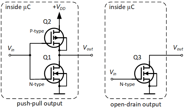
Standard digital outputs with external LEDs (push-pull mode)
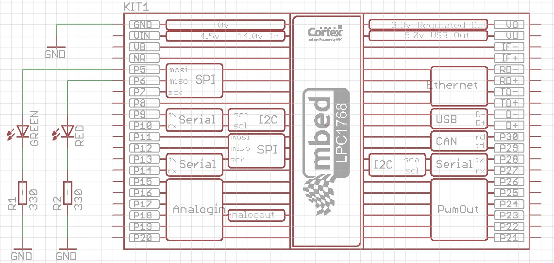
You will be using two schematics in this exercise to compare two different digital output modes. Digital input modes will also be compared in the next exercise.
Note
You will need two LEDs, two 220 or 330 Ohm resistors, SPDT and SPST mechanical switches (e.g. sliding switch and push button), optical transmissive and reflective sensors, some wires, breadboard and of course mbed board to complete the following exercises.
Very nice tutorial about switches (poles, throws, NO, NC, ...) can be found here.
Connect the components on the breadboard according to the following schematics:
Reminder
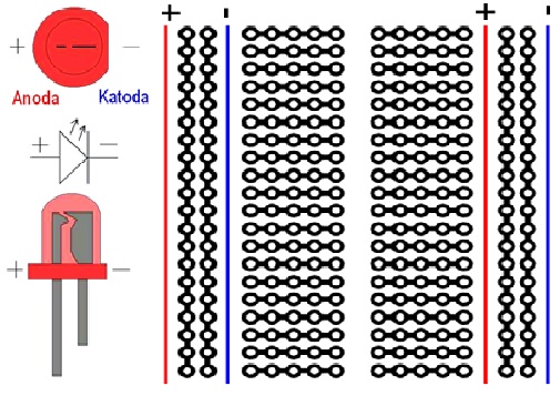
The following figure shows on the left side symbol of LED and its physical shape, so you can choose a right orientation when connecting it to the breadboard. The anode is longer pin and it connects to the power supply, and cathode is shorter pin and connects to the ground of the circuit. Also, the right side of the figure shows inner wiring of the breadboard.
Examine the following code:
#include "mbed.h"

DigitalOut green(p5);
DigitalOut red(p6);

int main() {
    while(1) {
        green = 1;
        red = 0;
        wait(0.5);
        green = 0;
        red = 1;
        wait(0.5);
    }
}
Notice that digital output pins (p5 and p6) are declared using DigitalOut class, which does not (yet) provide the option for setting the output mode. The default mode used in this case is standard (conventional) mode, which drives the output pin from internal power supply.
Run the program. You should see the flashings of the green and red LEDs every half second.
Digital outputs in open drain mode
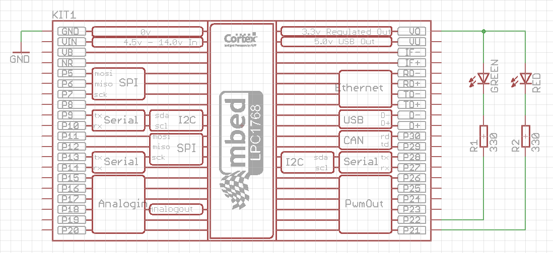
Connect the components on the breadboard according to the following schematics:
Examine the following code:
#include "mbed.h"

DigitalInOut green(p22, PIN_OUTPUT, OpenDrain, 1); // The first way of digital output configuration
DigitalInOut red(p21); // The second way of digital output configuration

int main() {
    red.output(); // Addition 1 for the second way of digital output configuration
    red.mode(OpenDrain);  // Addition 2 for the second way of digital output configuration
    red.mode(PullNone);  // Addition 3 for the second way of digital output configuration
    red = 1; // Turn red LED off (inverse logic)
    while(1) {
        green = 1;
        red = 0;
        wait(0.5);
        green = 0;
        red = 1;
        wait(0.5);
    }
}
In this way the digital output pins are configured as open drain outputs. A class used for this purpose is DigitalInOut, since the standard class DigitalOut does not (yet) have the option for open drain mode. DigitalInOut class has two constructors, and both of them are used and commented in the example code above.
You may also notice the inverse logic of this configuration. When the output is set to logic 1 state, a potential of that pin is 3.3 V, so the potential difference (voltage) accros the LED and resistor is zero and LED is off. When the output is set to logic 0, the potential of that pin drops to 0 V, and voltage across the LED and resistor becomes 3.3 V and LED turns on.
Be careful!
If you connect the LEDs in the open drain mode (the second schematics) and you do not configure the outputs to be in the open drain mode, there is a risk of damaging the mbed input circuitry or in the best case incorrect operation of the system. The open drain mode is usually used when a voltage needed to engage some actuator (e.g. relay) is larger than 3.3 V (e.g. 5 V, 12 V or 24 V). If the 3.3 V (with sufficient microcontroller's output current) is enough to engage the actuator, then both modes (standard and open drain) will work fine, but it is highly recommended to use the output modes correctly.
Digital input
Two most often used pull modes of digital inputs are depicted on the following figure:
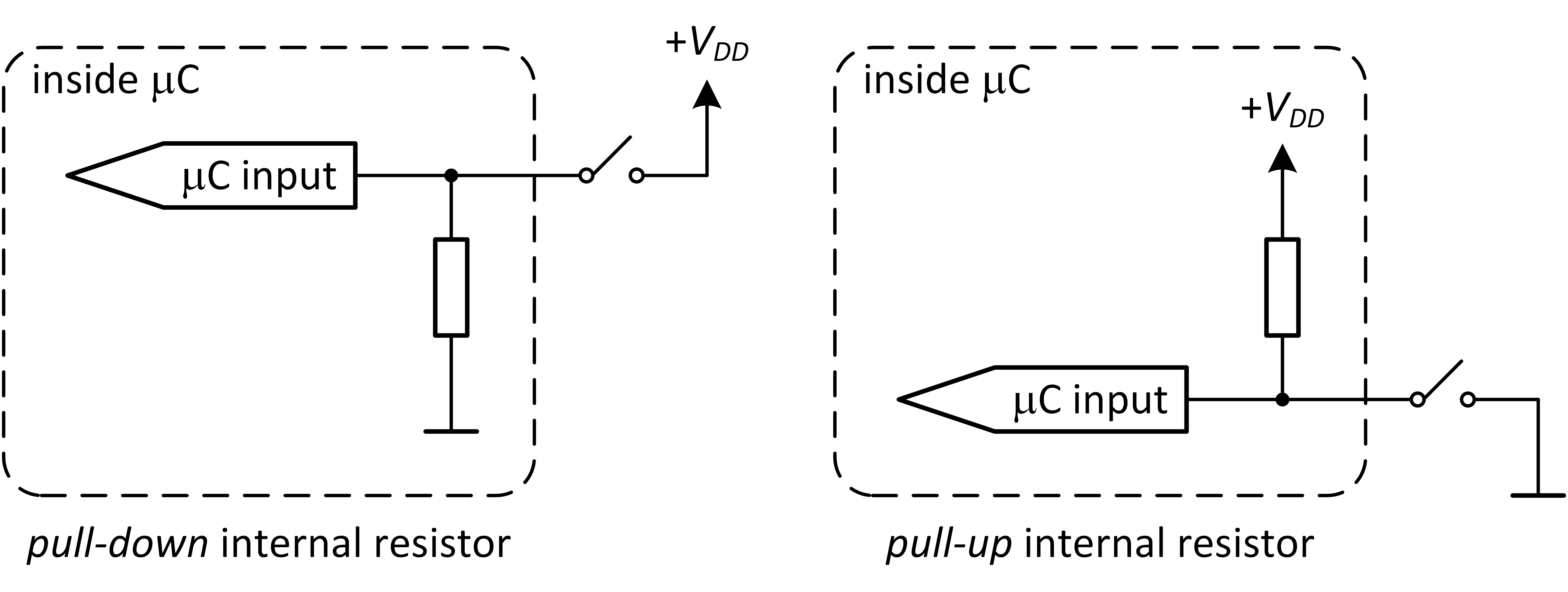
Pull-none mode does not contain the resistor at all. In the following exercises you will learn how to configure digital input modes properly.
Add a single-pole double-throw switch to the first schematics with LEDs, as shown in the following figure:
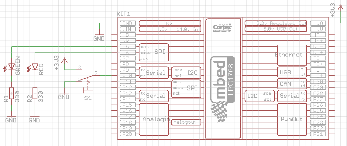
Examine the following code:
#include "mbed.h"

DigitalOut green(p5);
DigitalOut red(p6);
DigitalIn switchInput(p10);

int main() {
    int switchState;
    while(1) {
        switchState = switchInput; // read the input state only once in the while loop
        if(switchState == 0) {
            green = 0; // green LED off
            red = 1; // flash red LED
            wait(0.5);
            red = 0;
            wait(0.5);
        } else if (switchState == 1) {
            red = 0; // red LED off
            green = 1; // flash green LED
            wait(0.5);
            green = 0;
            wait(0.5);
        } else {
            // this case should not happen
            red = 1;
            green = 1;
        }
    }
}
Run the above program. You should see the red LED flashing when the switch S1 is in position #1, while the green LED is off, and vice versa when the switch is in position #3.
Now remove the wire that connects switch contact #1 with GND. Observe the behavior of the LEDs. You should see no difference comparing to the normal case. This means that the mbed input pin (p10) is connected to the GND internally, i.e. the pin is in the PullDown mode by default (we did not set the mode option at all).
Next, modify the program by setting the pin p10 into input mode PullUp. Immediately after the start of the main() function (line 8) add the following statement:
switchInput.mode(PullUp);
Run the modified program (leave the wire unconnected). You should now notice that the green LED flashes and the red LED is always off, regardless of the switch S1 state. The input pin p10 is internally pulled up when the switch S1 is in position #1.
Next, set the pin p10 into input mode PullNone (change the line 8 appropriately). Run the program and notice that the input pin p10 is now prone to external noise, static electricity or other electrical disturbances, when the switch S1 is in the position #1. The state of the LEDs are now unpredictable.
Finally, connect back the wire you removed and observe the behavior in all modes. The functionality of the program is now restored, regardless of the input mode set. To conclude this exercise, it is important to pull the input pin up or down (internally or externally) to have a reliable digital input state.
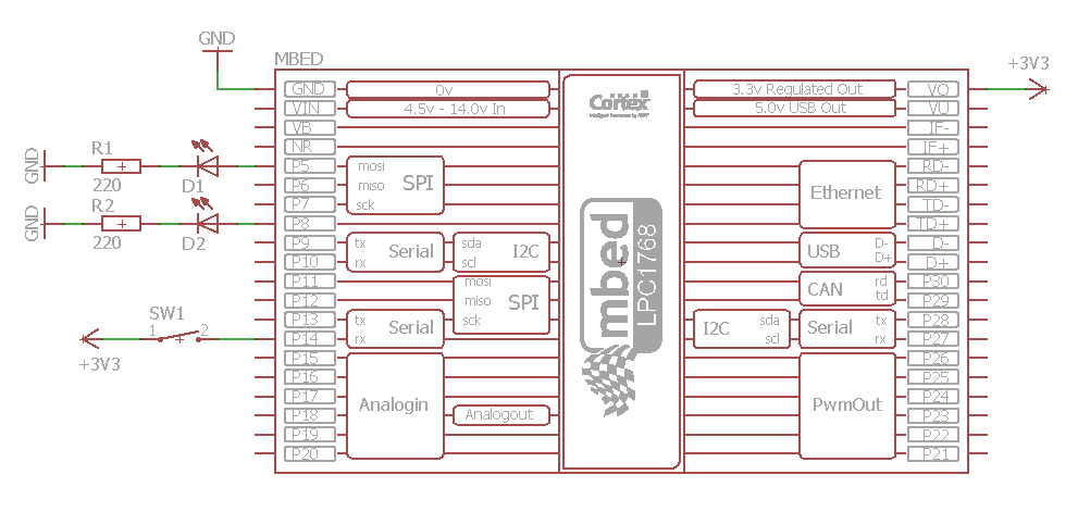
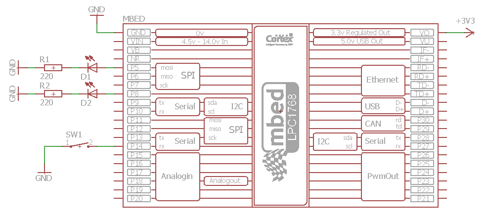
To conclude this exercise, replace the SPDT switch in the above schematics with SPST switch (push button), according to the following two schematics, and adjust the program accordingly to do the same tasks as above.
Counting events
In this exercise you will modify the above program to count the number of times the switch S1 has changed its state. If the count is less than 20, the green LED should be turned on and red off, and vice versa if the count is greater or equal to 20. Additionally, when the count reaches 20, wait 10 seconds after turning red LED on and reset the count to zero.
The code that solves this exercise is given below:
#include "mbed.h"

DigitalOut green(p5);
DigitalOut red(p6);
DigitalIn switchInput(p10);

int main() {
    int switchState, previousSwitchState = -1, x = 0;
    while(1) {
        switchState = switchInput; // read the input state only once in the while loop
        if (previousSwitchState == -1)  // first loop run
            previousSwitchState = switchState; // no changed state in the first loop run
        if (previousSwitchState != switchState)
            x++; // increase the count because the switch state is changed
        if(x < 20) {
            green = 1; // green LED on
            red = 0; //  red LED off
        } else {
            green = 0; // green LED off
            red = 1; //  red LED on
            wait(10);
            x = 0;
        }
        previousSwitchState = switchState; // refresh the previousSwitchState
    }
}
Analyze the code, run the program, and count how many times you need to change the switch S1 state for the red LED to turn on. You should expect this count to be 20, but in practice it will be much lower. The reason is a so called bouncing effect, which will be discussed later in the following exercises.
Congratulations!
You have completed all the exercises in the Digital inputs and outputs topic.
Return to TVZ Mechatronics Team Homepage.