Analog inputs and outputs
All exercises in this topic will be carried out using an mbed application board, but you can also use the breadboard and other external components. The application board has 3 inputs prepared for use with an AnalogIn class. Two potenciometers (Pot1 and Pot2) are connected to pins p19 and p20, respectively, and 3.5 mm audio jack is connected to pin p17.
Since mbed NXP LPC1768 has only one analog output on pin p18 for use with an AnalogOut class, mbed application board uses that output via another 3.5 mm audio jack.
In the following exericses you will examine the use of potenciometers as analog inputs, analog outputs, and analog communication between two mbeds.
Using potenciometers as analog inputs
Write a program that will read the inputs of potentiometers Pot1 and Pot2, calculate the average reading of two potentiometers, and based on the average reading value, turn on or off the four onboard mbed LEDs. Use the following table as rules for LEDs control:
| Average reading x | LED1 | LED2 | LED3 | LED4 |
| x <= 0.2 | 0 | 0 | 0 | 0 |
| 0.2 < x <= 0.4 | 1 | 0 | 0 | 0 |
| 0.4 < x <= 0.6 | 1 | 1 | 0 | 0 |
| 0.6 < x <= 0.8 | 1 | 1 | 1 | 0 |
| 0.8 < x <= 1 | 1 | 1 | 1 | 1 |
Write your own solution of the program, test it and then compare to the solution given below.
Import programMAB_Potenciometers
Using potenciometers as analog inputs.
Generating sawtooth waveform using analog output
Write a program that generates a simple sawtooth waveform.
One possible solution is given in the program below.
Import programMAB_Waveforms_A
A simple sawtooth waveform generator using analog output.
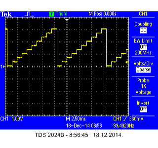
The oscillogram is shown in the following figure:

Smoothing the staircase waveform
Modify the above program to generate smoother sawtooth waveform, with the period kept the same (10 ms). Let the smoothness of the waveform be defined by the potentiometer Pot1, with a value of 0 meaning the above case (not smoothed), and a value of 1 meaning nice smooth waveform.
The solution is given in the program below.
Import programMAB_Waveforms_B
A sawtooth waveform generator using analog output, with smoothness setting over potentiometer.
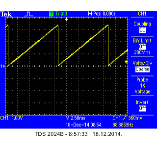
The oscillogram for Pot1 set to a value of 1 (maximum number of points) is shown in the following figure:

Generating sinewave waveform
Write a new program that will generate the sinewave waveform with mean value of 1.65 V, peak-to-peak amplitude that can be adjusted over potentiometer Pot1 in the range between 0 and 3.3 V, and frequency that can be adjusted over potentiometer Pot2 in the range between 10 and 20 Hz.
The solution is given in the below program.
Import programMAB_Waveforms_C
A simple sinewave generator with adjustable amplitude and frequency over potentiometers.
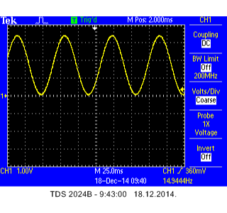
A sample oscillogram is shown in the figure below:

Congratulations!
You have completed all the exercises in the Analog inputs and outputs topic.
Return to TVZ Mechatronics Team Homepage.
