You are viewing an older revision! See the latest version
NAMote 72 wiki
Overview
This Wiki page describes how to setup a NAMote 72 platform and implementing the available test code.
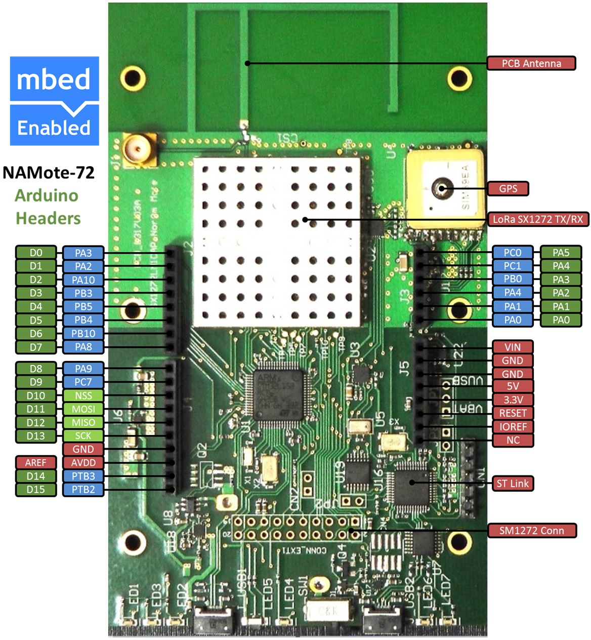
The pinout diagram below shows the commonly used interfaces and their locations.

Connecting and programming the NAMote72
1. Connect the micro USB connector to the NAMote72 USB2 Input and the other end to a PC
Download the appropriate "Hello World!" binary:
- <platform-name>: HelloWorld_<platform-name>.bin
Note: the source code for this program will be seen in the next section.
Save the program binary file to your mbed Microcontroller Disk, just like you would with a normal USB disk. The Status LED will flash as the PC writes the file to the Microcontroller disk. The file is now consumed.
2. Press the Reset Button
When the Reset Button in pressed, the microcontroller will be reset and the last programmed application will begin to run.
3. Hello World!
The Microcontroller is now running the program; flashing LED1 forever! If you reset the Microcontroller, or disconnect and reconnect the power, the program will simply restart.
Hello World!
Import programmbed_blinky
The example program for mbed pin-compatible platforms
Where Next
Follow the guide to creating your own programs using the online compiler
Technical Reference
Power
- USB powered or 4.5v - 9v on Vin pin
- Current (active): < _ _ _ mA
- Current (sleep): < _ _ _ mA
- 3.3v regulated output on VOUT to power peripherals
- 5.0v from USB available on 5v (only available when USB is connected unless extra regulator is added!)
- Digital IO pins are 3.3v, 4mA each, 400mA max total
