NAMote 72 wiki
Introduction
This Wiki page describes how to use this SX1272 based NAMote72 platform. This platform represents a completely programmable LoRa end device solution with a built in mbed compatible programming interface and a LiOn battery and charger. This platform provides the user with a number of built in sensors including a GPS receiver, pressure transducer, touch sensor, accelerometer, and thermometer. The intent is to provide the user with a platform to demonstrate the capabilities of LoRa and LoRaWAN in both private and public networks when used with a LoRaWAN concentrator. With mbed, users can easily download and install existing code examples as well as develop their own custom code.
The heart of the platform is the SX1272 LoRa transceiver chip. It is configured to allow the user to select the PA_Boost port output providing from approximately 0dBm to 19dBm transmit power at the antenna port, or to select an on board power amplifier output, driven from the SX1272’s RFO port that can provide between 23 dBm to 30 dBm. A printed circuit board antenna is also included, as well as an RF connector that permits the use of an external antenna.
This SX1272 NorAm LoRa Mote platfrom can operate over a wide frequency range, including the 868 MHz European and the 902-928 MHz North American ISM bands. An appropriate antenna must be used for the selected operating band. Although primarily intended for LoRa applications, the user can also enable FSK mode for conventional or legacy applications. Coupled with a link budget in excess of 135 dB in FSK and in excess of 155 dB in LoRa, the NorAm LoRa Mote platform really offers the possibility of two modems in one single package. The NAMote72 platform can comply with both ETSI and FCC regulatory requirements.
An Arduino compatible interface is provided which enables the user to incorporate any of the widely available shields into their application.
The SX1272 based NAMote72 platform requires only a PC with a USB interface for programming and a USB compatible charger to recharge the internal battery.
Example Applications
The shipped NAMote72 platform is programmed with the SCPI Command Parcer application and is the default program example for the platofrm. The SCPI application allows for specific direct testing of the platform. For connectivity based applications please see the LMIC Transmit example for connecting to the LoRaWAN and transmitting GPS data. For device to device and serial monitor testing please use the NAMote72 Utility Package for serial data transfer command examples. Each of these applications can be found on the Test Code Applications section of this wiki page.
Built In Sensors
- GPS Receiver
- Touch Sensor w/ Proximity Detect
- Pressure Transducer
- Accelerometer
- Temperature Sensor
- Battery Voltage Monitor
Enclosure
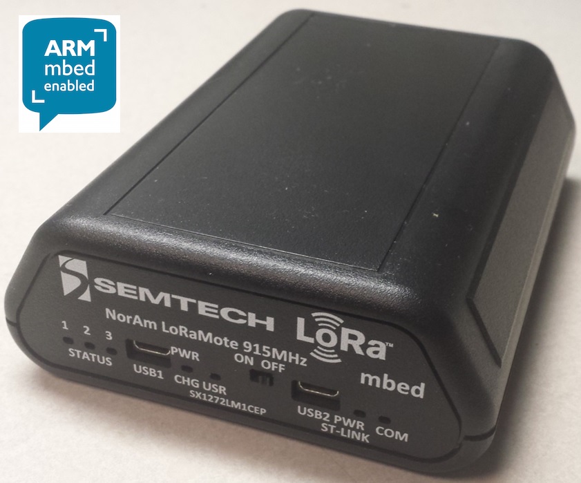
User Interface
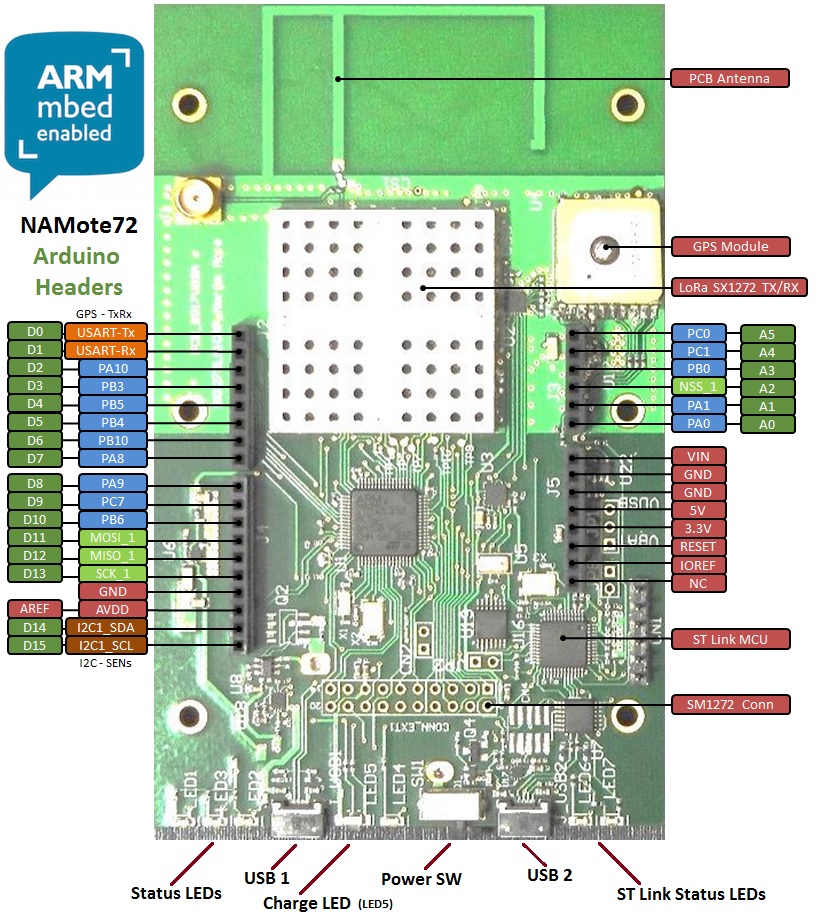
The SX1272 based NAMote72 platform is intended to enable a quick and easy range test of the SX1272 device. The front panel endplate and pinout diagrams below shows the commonly used interfaces and their locations.
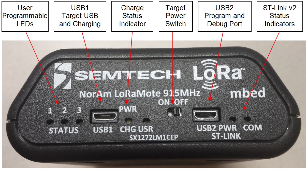 USB1 Charge Port - The USB1 Charger port connects to an external USB wall charger or host computer USB port. Under low battery conditions, the charger can supply up to 700mA to recharge the battery while also powering the module. This charge status indicator LED will illuminate orange when the battery is charging and green when fully charged.
User Configurable LEDs - There are four LEDs provided, which under user control can be used to provide module status. LED1 is red, LED2 is green, LED 3 is yellow and LED USR is red. The MCU ports for these LEDs are shown in the Appendix at the end of this wiki page.
Power Switch - This switches on the battery to power the module. When this switch is in the OFF position, and a charger is connected to USB1, all charge current is directed to the battery. When a charger is connected and the switch is on, a portion of the charge current charges the battery and a portion helps power the module.
USB2 Program/COM port - This port serves two functions. When connected to the Host PC through the USB cable, a mbed mass storage device will appear on the Host PC, permitting the user to program the module. In addition, a virtual com port will also appear, enabling serial communication with user firmware. The ST-Link status indicators show programming status. Green indicates successful download.
Inside the Enclosure
Connecting the Platform
1. Connect the micro USB connector to the NAMote72 USB2 Input (Images above) and the other end to a PC
Note: The NAMote72 will start to run the application that is curently programmed.
2. Ensure Connecton to PC and NAMote72 Virtual Drive Listing

3. Open NAMote72 virtual drive and select MBED.HTM to go to NAMote72 mbed platform page.
Programming the Platfrom
1. Import the appropriate example (Test Code Application A - SCPI Command Parcer) into the mbed Compiler
See Test Code Application Example Code wiki Page below for how to use SCPI Command Parcer.
2. Select NAMote72 as the Platform and Compile Application
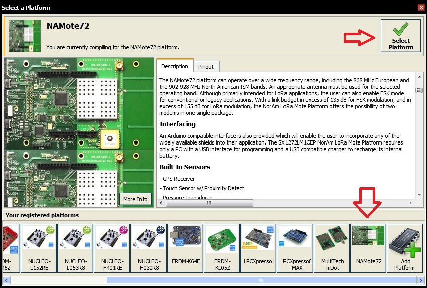
3. Select where to store the .bin programming file (in My Downloads by Default)
4. Programming the Platform
Move (save) the program binary file (.bin) to your mbed Virtual Disk Labeled NAMote72, just like you would with a normal USB disk. The Status LED will flash as the PC writes the file to the Microcontroller disk. The .bin file is now programmed into the platform.
5. The microcontroller will reset after programming and the last programmed application will begin to run.
Note: Test Code Applications require the use of a Serial Terminal Monitor (HyperTerm, Putty, TeraTerm, etc.)
6. Determing the Virtual COM port that the NAMote72 platform is using
Verify with Windows Device Manager and Ports available. Note the Port number.
7. Setup Serial Terminal Monitor
See mbed link for serial terminal monitor applications that are recommended ->.
https://developer.mbed.org/handbook/Terminals
Test Code Applications
See wiki page for each test code application example for a detailed description on how to use the code.
Test Code Application A - SCPI command Parcer (Default Example on NAMote72)
This (scpi) program below implements a SCPI command parser. When connected via the debug virtual comm port, commands can be sent to the radio and peripherals to perform specific tasks or to set specific parameters. The serial port defaults to 9600bps N-8-1.
Import programscpi_sx127x
SCPI interface to SX1272 and SX1276
Test Code Application B - Class-A end-device example using NAmote-72 with GPS
Import programLoRaWAN-NAMote72-Application-Demo
Demonstration of Class-A LoRaWAN device using NAMote-72
Test Code Application C - Serial Terminal Commands for NAMote72 HW
This program implements a serial terminal command environment. When connected via the debug virtual comm port, commands can be sent to the radio and peripherals to perform specific tasks or to set specific parameters. The serial port defaults to 57600 baud at N-8-1.
Import programNAMote72_Utility
NAMote72 Utility Application – Serial Terminal Monitor control for NAMote72 (note: this application replaces the previous na_mote1 test code application)
Where to Next
Follow the guide to creating your own programs using the online compiler
Schematics
NAMote72 Platform Schematic Sheets
Additional Information for the NAMote72
Semtech SX1272 RF Transceiver Web Link
http://www.semtech.com/wireless-rf/rf-transceivers/sx1272/
Semtech Documents
SX1272 Datasheet
LoRa Modem Designer's Guide
LoRa Low Energy Design Guide
LoRa Calculator: fast evaluation of link budget, time on air and energy consumption
Firmware
NAMote72 Firmware Update Files
Firmware update procedure: Run the batch (.bat) file contained withing the .zip file. Note: In updating the NAMote72’s with this batch file the first time it is run the ST Link driver will be updated. Then the batch file will need to be run again to update the NAMote72’s volume name and MBED.HTM link to the NAMote72’s platform page.
Appendix
MCU Port Assignments
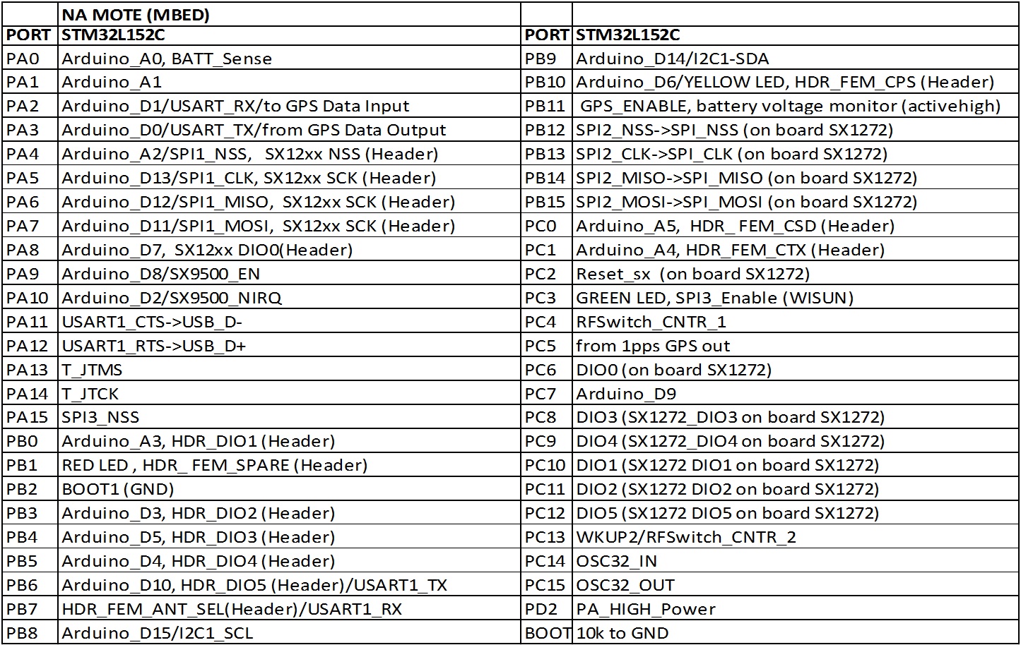
LED Settings

GPS / Battery Voltage Monitor Settings

TR Switch / PA Power Settings

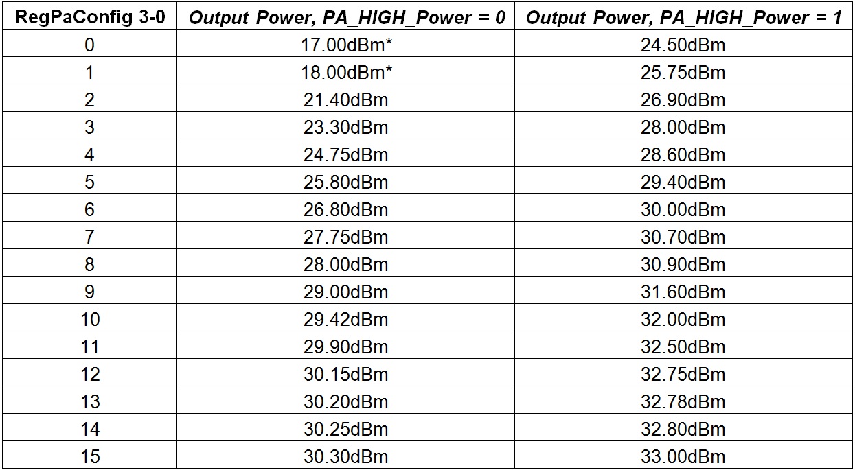
Output Power Level Settings +/-1dBm Settings
*Use PA_Boost for power 18dBm or lower.
