You are viewing an older revision! See the latest version
NAMote 72 wiki
Overview
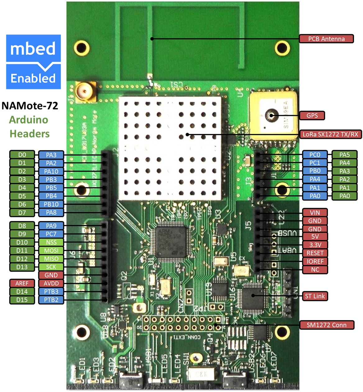
This Wiki page describes how to setup a NAMote 72 platform and implementing the available test code.
The pinout diagram below shows the commonly used interfaces and their locations.
Features
- Specific MCU Name and Part Number
High performance ARM® Cortex™-Mx Core
<system_core_clock>, <sizeof RAM>, <sizeof FLASH>
USB (Host/Device)
SPI (num of exposed)
I2C (num of exposed)
UART (num of exposed)
PWM (num of exposed)
ADC (resolution and MUX to peripheral ratio)
DAC (resolution and MUX to peripheral ratio)
GPIO (cnt)
- <platform-name> Onboard Sensors
Sensor 1
Sensor 2
- Evalution Form factor
<size>
<power options>
On-board (attachable, optional, etc...) Debug and Programming Interface Circuit
* [USB MSC] Drag-n-drop programming
* [USB CDC] USB Serial Port
* [USB HID] CMSIS-DAP
Firmware
Firmware update instructions or link to team wiki pages with instructions on how to update
Getting Started with mbed
1. Connect your microcontroller to a PC
Use the USB lead to connect your mbed to a PC. The status light will come on, indicating it has power. After a few seconds of activity, the PC will recognise the mbed Microcontroller as a standard USB drive.
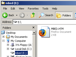 | 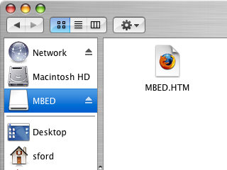 |
| Windows XP example | Mac OS X example |
2. Click the MBED.HTM link to get logged in
Go to the new USB Drive, and click MBED.HTM to open it in a web browser.
If you do not have an mbed account, choose "Signup", and create your mbed Account. Otherwise, log in with your normal username and password.
This will give you access to the website, tools, libraries and documentation.
PC Configuration
Your mbed Microcontroller can appear on your computer as a serial port. On Mac and Linux, this will happen by default. For Windows, you need to install a driver:
Windows
See Windows-serial-configuration for full details about setting up Windows for serial communication with your mbed Microcontroller
From a host PC to communicate with mbed you will need a terminal application. This allows the mbed Microcontroller to print to your PC screen, and for you to send characters back to your mbed.
- Terminals - Using Terminal applications to communicate between the Host PC and the mbed Micrcontroller
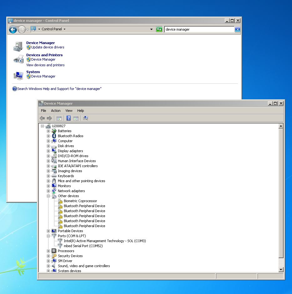
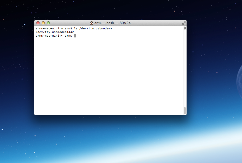
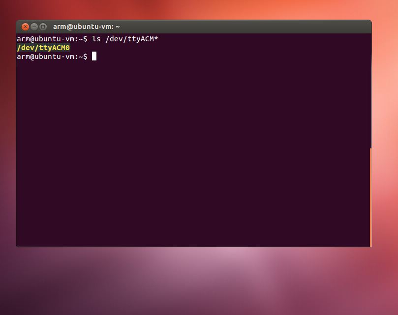
Some terminal programs (e.g. TeraTerm) list the available serial ports by name. However, if you do need to know the identity of the serial port so that you can attach a terminal or an application to it:
| Windows | Mac | Linux |
| Find the identity of the COM port by opening ''Device Manager''. To do this navigate ''Start -> Control Panel -> System -> Hardware -> Device Manager''. | To find the device name under Mac OS X, use the command ''ls /dev/tty.usbmodem*'' | To find the device name under Linux, use the command ''ls /dev/ttyACM*'' |
 |  |  |
Downloading A program
1. Save a program binary (.bin) to the Platform
Download the appropriate "Hello World!" binary:
- <platform-name>: HelloWorld_<platform-name>.bin
Note: the source code for this program will be seen in the next section.
Save the program binary file to your mbed Microcontroller Disk, just like you would with a normal USB disk. The Status LED will flash as the PC writes the file to the Microcontroller disk. The file is now consumed.
2. Press the Reset Button
When the Reset Button in pressed, the microcontroller will be reset and the last programmed application will begin to run.
3. Hello World!
The Microcontroller is now running the program; flashing LED1 forever! If you reset the Microcontroller, or disconnect and reconnect the power, the program will simply restart.
Hello World!
Import programmbed_blinky
The example program for mbed pin-compatible platforms
Where Next
Follow the guide to creating your own programs using the online compiler
Technical Reference
Power
- USB powered or 4.5v - 9v on Vin pin
- Current (active): < _ _ _ mA
- Current (sleep): < _ _ _ mA
- 3.3v regulated output on VOUT to power peripherals
- 5.0v from USB available on 5v (only available when USB is connected unless extra regulator is added!)
- Digital IO pins are 3.3v, 4mA each, 400mA max total
