Important changes to repositories hosted on mbed.com
Mbed hosted mercurial repositories are deprecated and are due to be permanently deleted in July 2026.
To keep a copy of this software download the repository Zip archive or clone locally using Mercurial.
It is also possible to export all your personal repositories from the account settings page.
Dependencies: LoRaWAN-lib mbed lib_mpl3115a2 lib_mma8451q lib_gps SX1272Lib
Dependents: LoRaWAN-NAMote72-BVS-confirmed-tester-0-7v1_copy
Homepage
LoRaWAN-NAMote72 Application Demo is a Class-A device example project using LoRaWAN-lib and SX1272Lib libraries.
This project is compliant with LoRaWAN V1.0.1 specification.
Comissioning.h (LoRaWAN Network Configuration)
The end-device can be activated in one of the two ways:
Over the Air (OTA) activation can be enabled as shown in the figure below.

The end-device must be configured with the following parameters:
LORAWAN_DEVICE_EUI(8 Bytes) : Fist 3 Bytes is the Organizationally Unique Identifier (OUI) followed by 5 bytes of unique ID. If not defined by user, then the firmware automatically assigns one to the end-deviceLORAWAN_APPLICATION_EUI(8 Bytes)LORAWAN_APPLICATION_KEY(or DEVKEY) (16 Bytes)

Activation by Personalization (ABP) can be enabled as shown in the figure below.

The end-device must be configured with the following parameters:
LORAWAN_DEVICE_ADDRESS(4 Bytes) : If not defined by user, then the firmware automatically assigns one to the end-deviceLORAWAN_NWKSKEY(16 Bytes)LORAWAN_APPSKEY(16 Bytes)

Config.h (LoRaWAN Communication Parameters)
- Mode of Operation : Hybrid
If the end-device needs to be configured to operate over 8-channels, then
Hybrid Modeneeds to be enabled
- Mode of Operation : Frequency Hop
If the end-device needs to be configured to operate over 64-channels, then
Hybrid Modeneeds to be disabled
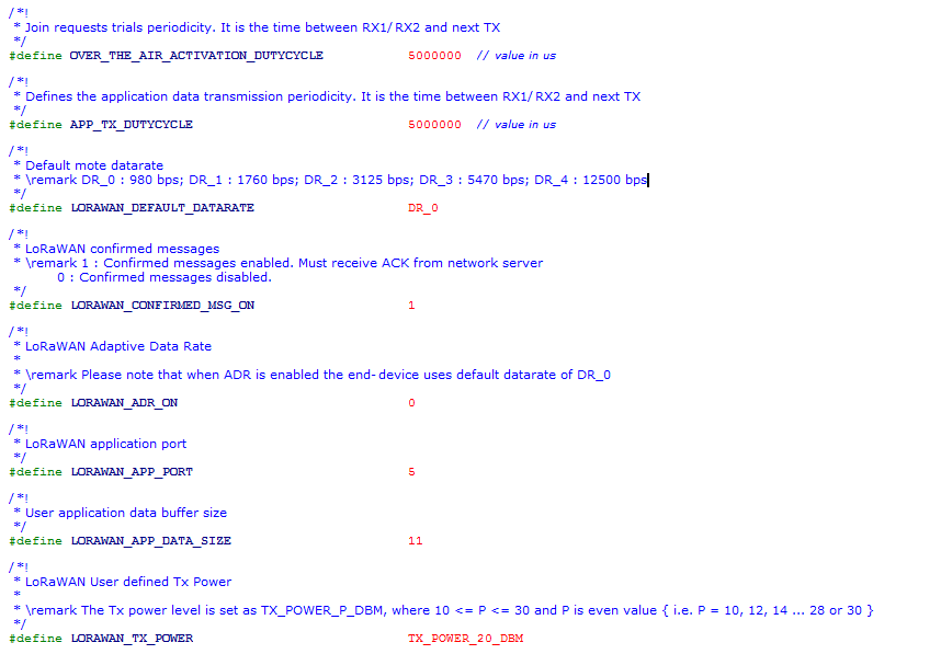
- Delay between successive JOIN REQUESTs :
The delay between successive Join Requests (until the end-device joins the network) can be configured using the parameter
OVER_THE_AIR_ACTIVATION_DUTYCYCLE
- Inter-Frame Delay :
One can change the delay between each frame transmission using
APP_TX_DUTYCYCLEIt is advisable thatAPP_TX_DUTYCYCLEis greater than or equal to 3sec.
- Data Rate :
The data rate can be configured as per LoRaWAN specification using the paramter
LORAWAN_DEFAULT_DATARATE. The range of values are DR_0, DR_1, DR_2, DR_3 and DR_4
- Confirmed/Unconfirmed Messages :
The uplink message or payload can be chosen to be confirmed or unconfirmed using the parameter
LORAWAN_CONFIRMED_MSG_ON. When set to 1, the transmitted messages need to be confirmed with anACKby the network server in the subsequent RX window. When set to 0, noACKis requested.
- ADR ON/OFF :
The ADR can be enabled or disabled using the parameter
LORAWAN_ADR_ON. When set to 1, ADR is enabled and disabled when set to 0.
- Application Port :
The application port can be set using parameter
LORAWAN_APP_PORT.
- Payload Length :
The lenght of the payload (in bytes) to be transmitted can be configured using
LORAWAN_APP_DATA_SIZE
- Transmit Power :
The transmit power can be configured using
LORAWAN_TX_POWER(LoRaMAC verifies if the set power is compliant with the LoRaWAN spec and FCC guidelines)

Main.cpp (Device State Machine)
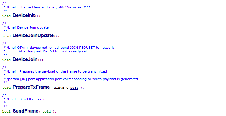
The end-device state machine is defined.
- Initial State : Device is initialized.
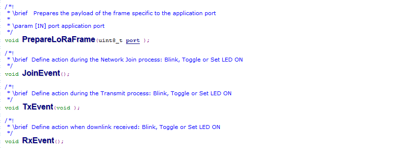
- Join State : For OTA, Join Request is transmitted to the network until Join Accept is received by the end-device. Join event function is called that sets Red LED ON.
- Send State : Transmit payload frame is prepared. Tx event is called that blinks the Red LED indicating uplink transmission.
- Cycle State : Next packet transmission is scheduled
LoRaEventProc.cpp (Events and On-board Application)
Define events during Join, Tx & Rx. Prepare TX packet by appending with appropriate application data.

- PrepareLoRaFrame(uint8_t port ) :
Prepare LoRa payload frame with on-board application data such as GPS, Temperature, Battery, etc. LoRa.ApplicationCall(AppType ) calls application AppType defined in
LoRaApp.cpp. AppType is defined inLoRaApp.h

LoRaApp.cpp
User-defined applications such as GPS, Temp, Accelerometer, LED indications etc. Event based actions such as LED blink on Tx, LED toggle on downlink etc

LoRaDeviceStateProc.cpp
Process function calls corresponding to different Device states

LoRaMacLayerService.cpp
Define MAC Layer Services: MLME & MCPS
Serial Terminal Display
By using a serial port connection using applications such as teraterm or putty, one can view the status of the End-Device. Once the End-Device Joins the network, transmission parameters such as payload data, application port, message type etc. are displayed on the terminal.

Default Application Payload
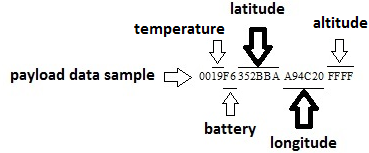
This application defaults to sending uplink data to logical port 5. The application payload consists of:

Sample Application Payload Calculation for Longitude/Latitude
Payload => 00 19 F6 352BBA A94C20 FFFF
Temperature Calculation
19H => 2510
Temp = 25/2 = 12.5 oC
Battery Level
FFH => 100 %
F6H => 96.5 %
Longitude Calculation
longitude = A94C20H => 1109507210
longitudinal coordinate = -360 + (longitude10 x 180/(223))
longitudinal coordinate = -121.93
Latitude Calculation
latitude = 352BBAH = 348460210
latitude coordinate = (latitude10 x 90/(223-1))
latitude coordinate = 37.39