Important changes to repositories hosted on mbed.com
Mbed hosted mercurial repositories are deprecated and are due to be permanently deleted in July 2026.
To keep a copy of this software download the repository Zip archive or clone locally using Mercurial.
It is also possible to export all your personal repositories from the account settings page.
Guide for Any Platform
This Wiki page provides a detailed guide on how to setup and operate PixArt's PAT9125EL sensor with any platform.
Hardware

NOTE: This image shows the Nordic nRF52-DK microcontroller as an example.
- 1.) PC with Windows Operating System
- 2.) Any Microcontroller & Associated Cables (often USB-A male to USB-B male or USB-A male to micro-USB male)
- 3.) PAT9125EL Evaluation Board
- 4.) Standard Male Pin Headers
- 5.) Jumper Cables
- 6.) Soldering Station
- NOTE: PC and soldering station not included in image.
- You will need to solder the pin headers to the evaluation board similar to the following image:
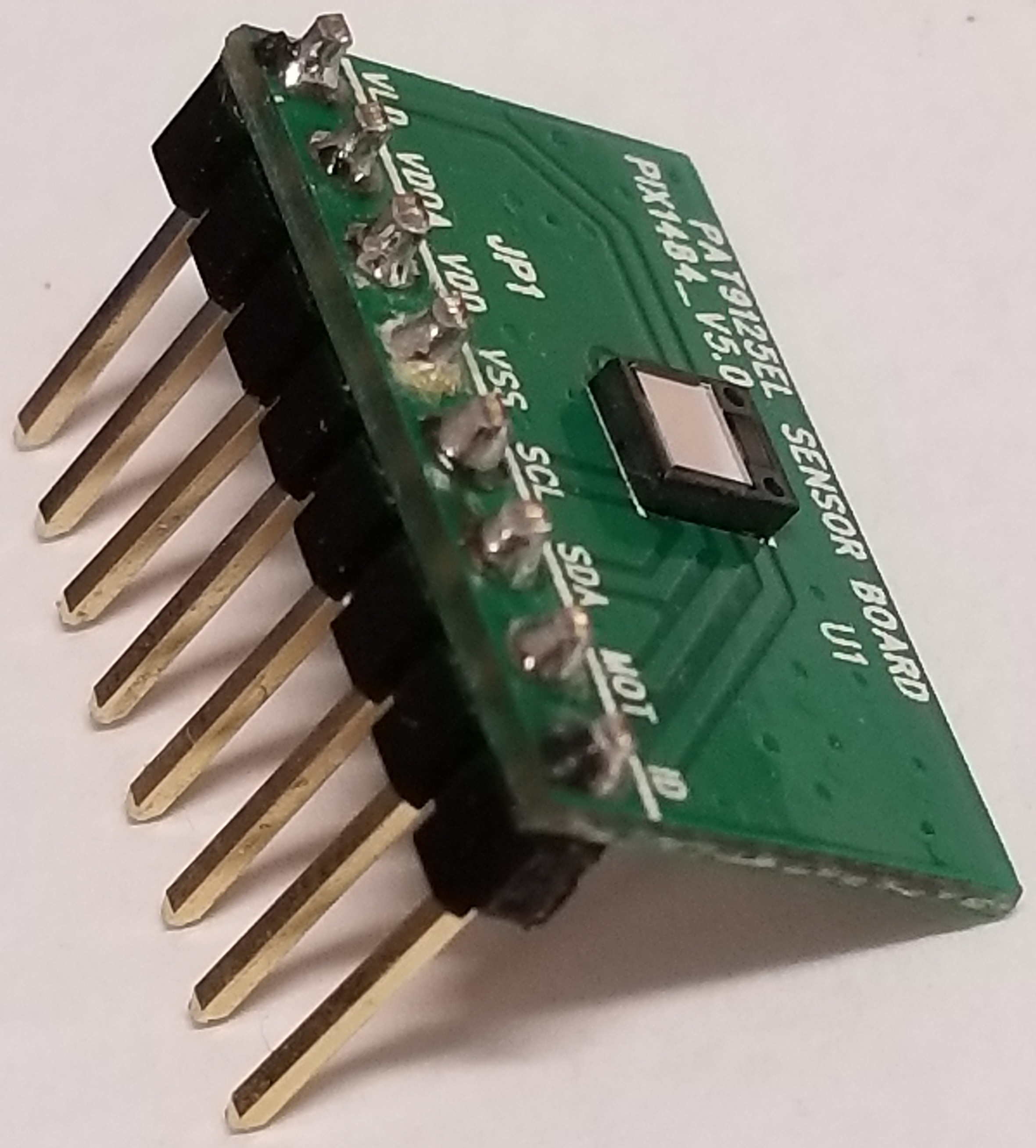
- You will need to solder the pin headers to the evaluation board similar to the following image:
- NOTE: PC and soldering station not included in image.
Importing Code
First, we need to import code into the microcontroller to start talking to the sensor. For the firmware code, please visit this product's components page here:
https://os.mbed.com/components/PAT9125EL-Evaluation-Board/
- 1.) Login/create an mBed account.
- 2.) Import the reference firmware into mBed's online compiler using the "Import program" button. You can find this in the link above.

- 3.) Make sure the selected platform is the platform that you are using.
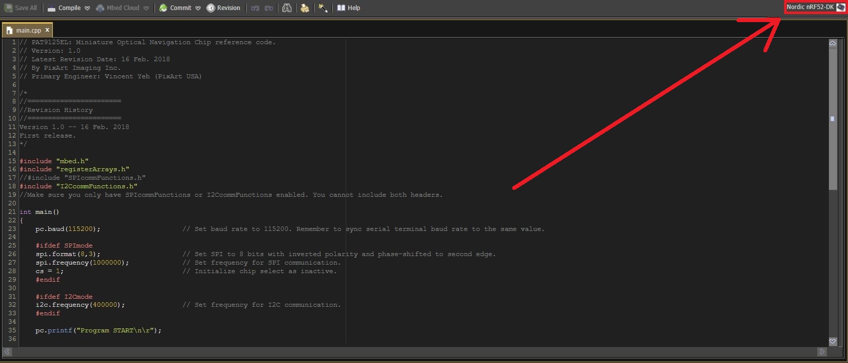
- 4.) Make sure that you are using the proper library. Only one of the SPI/I2C libraries should be in use. Simply comment out the one that is not in use.

- 5.) Make sure your microcontroller is plugged into your PC. It should show up as a separate drive similar to the (C:) drive. Then, you can compile the program and save the HEX file into your microcontroller.

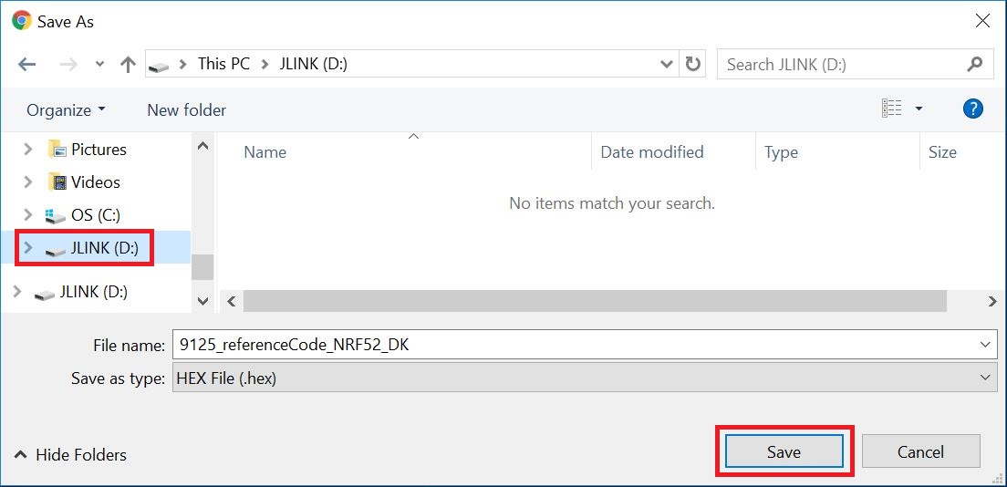
- NOTE: If you suspect your code did not import properly, please try unplugging the device, plugging it back in, and then re-compiling and saving the code into the device.
Connection
Please refer to the images and notes below for details on how to connect your hardware.
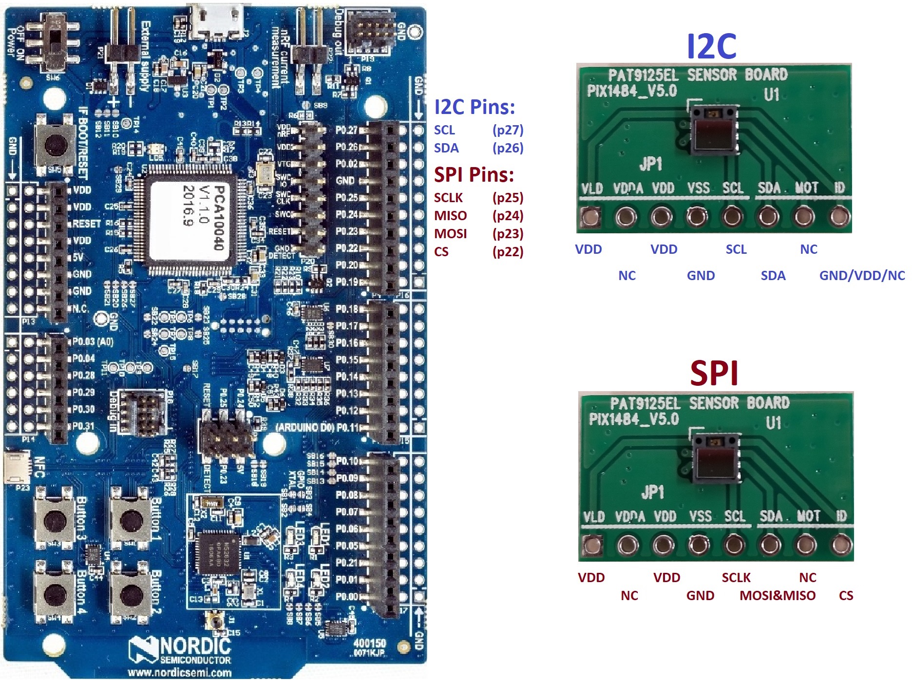


The above images show how the sensor connects to the Nordic nRF52-DK as a template. To connect it to your own microcontroller of choice, please follow these steps:
- 1.) First make sure you have chosen the platform that you have. See step 3 in the "Importing Code" section.
- 2.) First make sure you are using the right protocol for your hardware (I2C or SPI). See step 4 in the "Importing Code" section.
- 3.) Assign any GPIO pins on your microcontroller to the I2C/SPI pins you want.
- For I2C: change "static I2C i2c(p26, p27);" to "static I2C i2c( [any_pin], [any_pin] );"
- For SPI: change "static SPI spi(p23, p24, p25);" to "static SPI spi( [any_pin], [any_pin], [any_pin] );"
- You will also need to change "static DigitalOut cs(p22);" to "static DigitalOut cs( [any_pin] );"
- 4.) With pins properly assigned, simply use jumper cables to connect them to the corresponding pins on the PAT9125EL evaluation board.
===Other notes:===
- VDD and VLD on the PAT9125EL evaluation board connect to any 3.3V VDD pin on your microcontroller.
- GND on the PAT9125EL evaluation board connect to any GND pin on your microcontroller.
- NC = No connection.
- NOTE: For the SPI version, you will need a 2-to-1 connection because this sensor uses 3-Wire SPI (data pin "SDA" on the evaluation board is bi-directional). The SDA pin on the evaluation board needs to connect to BOTH the MISO and MOSI pin that have you assigned to your microcontroller.
- NOTE: For the I2C version, the "ID" pin on the evaluation board determines the slave ID depending on what it is connected to. (High = 0x73, Low = 0x75, NC = 0x79). By default, please connect this pin to GND (Low) unless you have altered the firmware.
- To change the slave ID in firmware, you will need to alter the second line of code in I2CcommFunctions.h

- To change the slave ID in firmware, you will need to alter the second line of code in I2CcommFunctions.h
Functional Test
- 1.) You will need a terminal emulator program. The one used in this guide will be Tera Term. If you do not already have it, you can find it at this link:
https://en.osdn.jp/projects/ttssh2/releases/
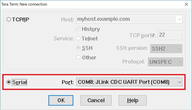
- 2.) Open Tera Term and go to File > New Connection or use the hotkey "Alt + N". Select "Serial" and choose the COM port corresponding to your microcontroller. Then click on "OK".
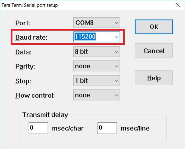
- 3.) Go to Setup > Serial Port and set the baud rate to 115200. Then click on "OK".
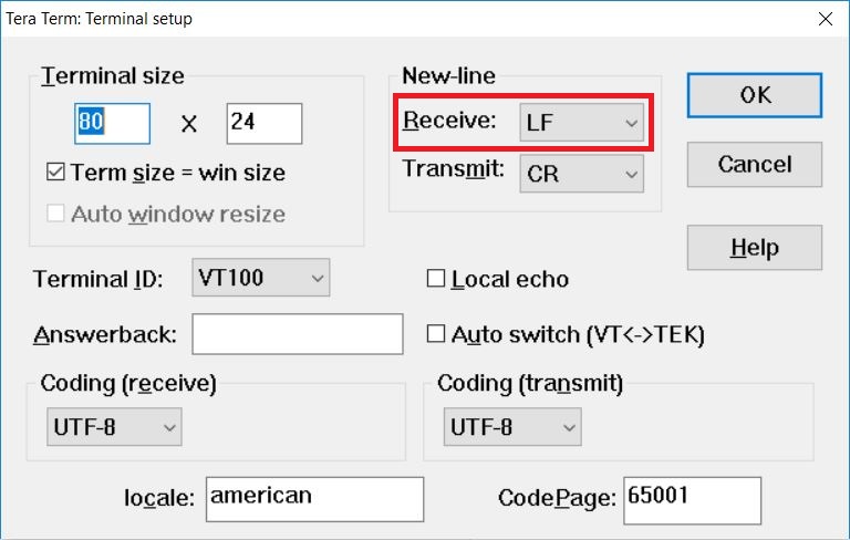
- 4.) Go to Setup > Terminal and change "Receive" from "CR" to "LF". Then click on "OK".
- 5.) With the hardware wired up properly, the firmware loaded into the microcontroller, and the terminal emulator set up, we should now be able to see the sensor working. If you move your finger in front of the sensor (remember the working distance is 1-30mm), you should see outputs on the terminal:
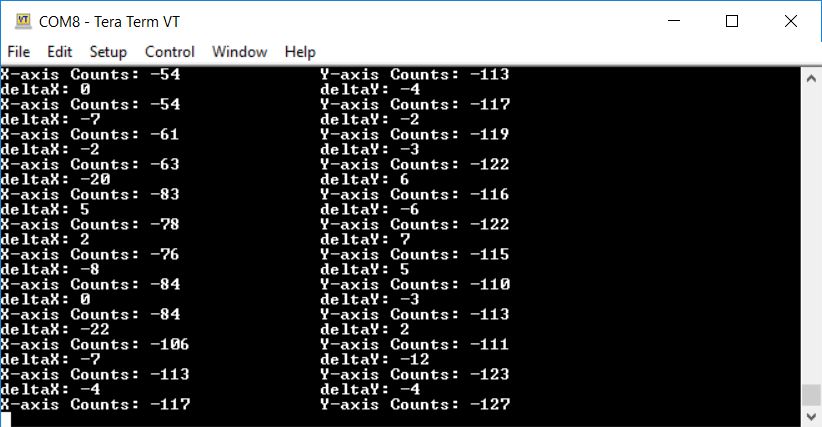
- "deltaX" and "deltaY" show the number of counts detected per report.
- "X-axis Counts" and "Y-axis Counts" show the total number of counts recorded throughout runtime.
Thank you for choosing PixArt! If you have any questions, feel free to contact us at: sales_us@pixart.com.