Como hacer un Piccolo
En la siguiente documentación plantearemos como hacer un Piccolo, para ello empezaremos con lo básico
¿Qué es un Piccolo?
Piccolo es un CNC de bolsillo que nos sirve para dibujar en 2D, formas o figuras que le pidamos, trabaja en base a movimientos de 3 servo motores que nos permiten realizar el dibujo y un engranaje sencillo de piñones para dar dirección a nuestra herramienta de dibujo, esta puede ser un lápiz, marcador, bolígrafo, etc.
Materiales para elaborar un Piccolo
- 3 Micro Servo SG90
- 8 Tornillos de cabeza plana M3 de 10 mm
- 3 Tornillos de cabeza plana M3 de 16 mm
- 2 Tornillos M3 de 10 mm
- 4 Tornillos M3 de 22 mm
- 17 Tuercas de bajo perfil M3
- 1 Llave hexagonal de 2.5 mm
- 1 Llave hexagonal de 2 mm
- 1 Cable USB microB
- 1 Banda elástica
- 2 Ataduras de cables (opcional)
- 4 Pies de goma adhesiva de 6.4 mm (opcional)
- 1 Tarjeta Nucleo STM32F411
- Piezas de MDF: entre 2,75 y 3,10 mm
- Partes acrílicas: entre 2,90 y 3,20 mm
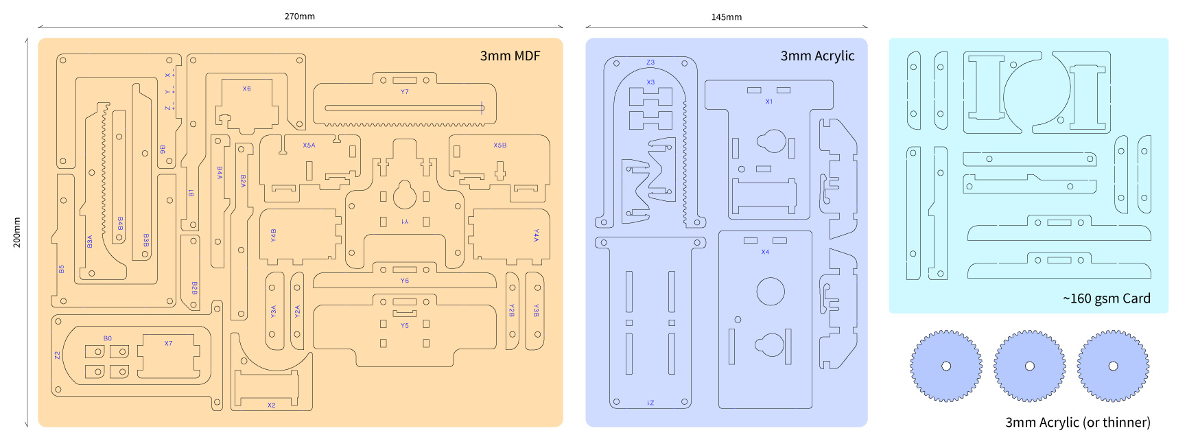
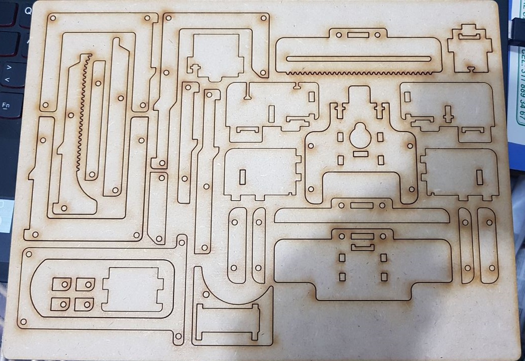
Para elaborar las piezas de corte de MDF y las partes acrílicas se necesita realizar un corte láser, a continuación el esquema de corte

A tener en cuenta: Los engranajes: iguales son más delgados que las otras partes acrílicas, pero mayores de 2 mm.
Para realizar la de forma correcta la fabricación del Piccolo, por favor visitar la guía oficial de fabricación
https://github.com/DiatomStudio/Piccolo/wiki/Piccolo-Fabrication-Guide

¿ Comó ensamblar el Piccolo?
Para el montaje del Piccolo dirigirse a:
https://github.com/DiatomStudio/Piccolo/wiki/Piccolo-Assembly-Instructions
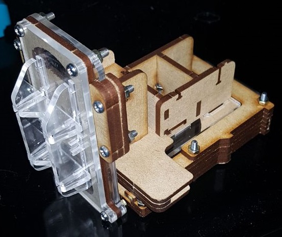
Y Seguir el paso a paso, debería quedar así:

Ahora programaremos nuestra Tarjeta NucleoSTM32F411
Para la compilación de la misma usaremos el compilador de Mbed y ahí crearemos nuestro código
Crearemos un nuevo archivo y empezaremos a programar
Primero importaremos las librerías que vamos a usar y habilitaremos los puertos que usaremos para conectar nuestros Servos
/***** Librerías *****/

#include "mbed.h"

/**************PUERTOS I/O DE SISTEMA EMBEBIDO NUCLEO-F411RE*******************/

#define DEBUG 1
Serial command(USBTX, USBRX);
DigitalOut led(LED1);
PwmOut myServoX(PB_3); //Servo X
PwmOut myServoY(PB_4); //Servo Y
PwmOut myServoZ(PC_7); //Servo Z
InterruptIn button(USER_BUTTON); // interrupcion boton stop
volatile bool button1_pressed = false;
volatile bool button1_enabled = true;
Ahora definiremos las variables
#define BUFF_SIZE 6         // Tamaño del comando enviado desde CoolTerm
#define COMM_N 0            //
#define INITPARAMETER  1    //  La primer variable que leera en nuestro array
#define MAXPOS 50           // Posicion maxima de la matriz de dibujo  x,y en mm
#define POSDRAW 30          // Posicion del servomotor Z  para dibujar
#define PI 3.1415926        // Definir el valor de PI
uint8_t RSTEP = 5;              // Ini. variable de Resolucion para el dibujo
uint8_t DET=1;
uint8_t  posx_old=0;     // Posición anterior del eje X
uint8_t  posy_old=0;     // Posición anterior del eje Y
uint8_t SSTIME = 100;  // Tiempo que se demora en ejecutar un dibujo
Ahora tenemos que definir que comando es que, cuando le enviemos la información por comando serial (consola)
#define LED_NC          0
#define DOT_NC          1
#define LINE_NC         2
#define RECTANGULO_NC   3
#define CIRCLE_NC       4
#define HOME_NC         5
#define RESOLUCION_NC   6
#define TIEMPOPASOS_NC  7
#define STOP_NC         8
#define PAUSA_NC        9
#define REANUDAR_NC     10
Ahora crearemos las funciones para mover los servos X, Y, Z
int coord2pulse(float coord) // Convertir el movimiento de los motores (0 - 255)
    {
     if(0 <= coord <= MAXPOS)
        return int(750+coord*1900/50);// u6
   return 750;
    }

void vertex2d(float x, float y) // Funcion para enviarle la posicion a (x,y)
    {
    wait_ms(SSTIME);
    int pulseY = coord2pulse(y);
    int pulseX = coord2pulse(x);

    myServoY.pulsewidth_us(pulseY);
    myServoX.pulsewidth_us(pulseX);

    }

void draw() // Función para enviarle la posicion  de dibujo a Z, lo mueve hacia abajo.
    {
    wait_ms(SSTIME*10);
    int pulseZ=coord2pulse(POSDRAW);
    myServoZ.pulsewidth_us(pulseZ);
    wait_ms(SSTIME);
    }
void nodraw() // Función para enviarle la posicion de no dibujar a  Z, lo mueve hacia arriba.
    {
    wait_ms(SSTIME*10);
    int pulseZ=coord2pulse(0);
    myServoZ.pulsewidth_us(pulseZ);

    }

void initdraw(float x, float y) //Función para determinar desde donde inicia a dibujar el Piccolo como si existiera un plano cartesiano en el área del dibujo
    {
    vertex2d(x,y);
    wait_ms(SSTIME);
    draw();
}
Ahora creamos las funciones necesarias para leer lo que le enviamos a nuestro Piccolo en la consola
uint8_t buffer_command[BUFF_SIZE]={0,0,0,0,0,0}; // Matriz del Comando enviado, debe ser la misma cantidad de la variable definida anteriormente

void print_num(uint8_t val)   //
    {
    if (val <10)
        command.putc(val+0x30);
    else
        command.putc(val-9+0x40);
    }

void print_bin2hex (uint8_t val) // Imprimir el comando enviado en Hexadecimal
    {
    command.printf(" 0x");
    print_num(val>>4);
    print_num(val&0x0f);
    }

void Read_command() // Leer el comando que se digito en CoolTerm
    {
    for (uint8_t i=0; i<BUFF_SIZE;i++)
        buffer_command[i]=command.getc();
    }

void echo_command() //
    {
    for (uint8_t i=0; i<BUFF_SIZE;i++)
        print_bin2hex(buffer_command[i]);
    }

uint8_t check_command() // Verifica el ultimo valor del comando enviado '>'
    {
    if (buffer_command[BUFF_SIZE-1]== '>'){
        #if DEBUG
        command.printf("\nComando: ");
        print_bin2hex(buffer_command[COMM_N]);
        command.printf(" -> ");
        #endif
    return 1;
    }
        #if DEBUG
        command.printf("\n !!!!!!!!ERROR EN EL COMANDO!!!!!!!!!!!!!! -> ");
        echo_command();
        #endif
    return 0;
    }
Ahora agregamos las funciones para poder dibujar en el Piccolo
void Led(int tm) //Función para definir el tiempo de led en milisegundos
    {
    #if DEBUG
    command.printf("\nTiempo led: %i seg\n", tm);
    #endif
    led=1;
    wait(tm);
    led=0;
    }

void punto(uint8_t x, uint8_t y) //Función para dibujar un punto
    {
    #if DEBUG
    command.printf("\nCoordenadas  x=%i, y=%i\n",x,y);
    #endif
    initdraw(x,y);
    nodraw();
    }

void linea(float xi, float yi,  float  xf, float yf)
    {
    #if DEBUG
    command.printf("\nCoordenadas xi=%f, yi=%f, xf=%f, yf=%f, resolucion: %i \n", xi,yi,xf,yf,RSTEP);
    #endif
    float xp,yp;
    float m=(yf-yi)/(xf-xi);
    float b=yf-(m*xf);
    #if DEBUG
    command.printf("\n b =%f, m=%f \n", b,m);
    #endif
    float nstep =(m/RSTEP);
    //nstep=RSTEP;
    #if DEBUG
    command.printf("\nstep = %f \n", nstep);
    #endif
     if ((abs(xf-xi))>abs(yf-yi)){
        if (xf>xi){
           initdraw(xp,yp);
           for (xp=xi; xp<=xf; xp+=RSTEP){
            yp =m*xp+b;
            vertex2d(xp,yp);
            #if DEBUG
            command.printf(" CASO 1: ( dx>dy & xf>xi ) Coordenadas x=%f,y=%f \n", xp,yp);
            #endif
             } }
        else{
            float temp = xi;
            xi = xf;
            xf = temp;
            initdraw(xp,yp);
            for (xp=xi; xp<=xf; xp+=RSTEP){
            yp =m*xp+b;
            vertex2d(xp,yp);
            #if DEBUG
            command.printf(" CASO 2: ( dx>dy & xf<xi ) Coordenadas x=%f,y=%f \n", xp,yp);
            #endif
            }}}
    else {
          if (yf>yi){
           initdraw(xp,yp);
           for (yp=yi; yp<=yf; yp+=RSTEP){
            xp=(yp-b)/m;
            vertex2d(xp,yp);
            #if DEBUG
            command.printf(" CASO 3: ( dy>dx & xf>xi ) Coordenadas x=%f,y=%f \n", xp,yp);
            #endif
            }}
        else{
            float tempo = yi;
            yi = yf;
            yf = tempo;
            initdraw(xp,yp);
            for (yp=yi; yp<=yf; yp+=RSTEP){
            xp=(yp-b)/m;
            vertex2d(xp,yp);
            #if DEBUG
            command.printf(" CASO 4: ( dy>dx & xf<xi ) Coordenadas x=%f,y=%f \n", xp,yp);
            #endif
             }
         }
        }
    nodraw();
    }

void Rectangulo(uint8_t x, uint8_t y, uint8_t a, uint8_t h)
    {
    #if DEBUG
    command.printf("\nCoordenadas x=%i, y=%i, ancho=%i, alto=%i, resolucion=%i\n", x,y,a,h,RSTEP);
    #endif
    uint8_t A=x+a;
    uint8_t B=y+h;
    initdraw(x,y);

     for(uint8_t xi=x; xi<=(x+a); xi+=RSTEP){
         vertex2d(xi,y);
        #if DEBUG
        command.printf("Coordenadas x=%i,y=%i for 1\n", xi,y);
        #endif
        }
    for (uint8_t yi=y; yi<=(y+h); yi+=RSTEP){
        vertex2d(x+a,yi);
        #if DEBUG
        command.printf("Coordenadas x=%i,y=%i for 2\n", x+a,yi);
        #endif
        }
    for(uint8_t xf=A; xf>x; xf= xf - RSTEP){
         vertex2d(xf,B);
        #if DEBUG
        command.printf("Coordenadas x=%i,y=%i for 3\n", xf,B);
        #endif
        }
    for (uint8_t yf=(y+h); yf>y; yf-=RSTEP){
        vertex2d(x,yf);
        #if DEBUG
        command.printf("Coordenadas x=%i,y=%i for 4\n", x,yf);
        #endif
        }
        vertex2d(x,y);
        #if DEBUG
        command.printf("Coordenadas x=%i,y=%i for 4\n", x,y);
        #endif
    nodraw();
    }

void circle(uint8_t cx, uint8_t cy, uint8_t radio)
    {
    int y;
    int x;
    vertex2d(cx,cy);
    #if DEBUG
      command.printf("\nCoordenadas xc =%i, yc =%i, Radio=%i \n",cx,cy,radio);
     #endif

     for(double i=0; i<=PI/2 ;i+=((PI/2)/RSTEP))
      {
      x=radio*cos(i);
      y=radio*sin(i);
      initdraw(x+cx,y+cy);
      #if DEBUG
      command.printf("Coordenadas x =%li, y =%li, R=%i, Resolcion:%i \n",x+cx,y+cy,radio,((PI/2)/RSTEP));
      #endif
      }
       #if DEBUG
      command.printf("\n");
      #endif
  for(double i=PI/2; i<=PI ;i+=((PI/2)/RSTEP))
      {
      x=radio*cos(i);
      y=radio*sin(i);
      vertex2d(x+cx,y+cy);
      #if DEBUG
      command.printf("Coordenadas x =%li, y =%li, R=%i, Resolcion:%i \n",x+cx,y+cy,radio, ((PI/2)/RSTEP));
      #endif
      }
      #if DEBUG
      command.printf("\n");
      #endif
  for(double i=PI; i<=((3*PI)/2) ;i+=((PI/2)/RSTEP))
      {
      x=radio*cos(i);
      y=radio*sin(i);
      initdraw(x+cx,y+cy);
      #if DEBUG
      command.printf("Coordenadas x =%li, y =%li, R=%i, Resolcion:%i \n",x+cx,y+cy,radio,((PI/2)/RSTEP));
      #endif
      }
      #if DEBUG
      command.printf("\n");
      #endif
  for(double i=((3*PI)/2); i<=(2*PI) ;i+=((PI/2)/RSTEP))
      {
      x=radio*cos(i);
      y=radio*sin(i);
      initdraw(x+cx,y+cy);
      #if DEBUG
      command.printf("Coordenadas x =%li, y =%li, R=%i, Resolcion:%i \n",x+cx,y+cy,radio,((PI/2)/RSTEP));
      #endif
     }
 nodraw();
 }

void home()
    {
    nodraw();
    vertex2d(0,0);
     #if DEBUG
    command.printf("\nCoordenada HOME x=0, y =0");
    #endif
    }

void resolucion(int res) // Funcion para definir la resolucion del dibujo
    {
    RSTEP = res;
    #if DEBUG
    command.printf("\nResolucion definida en=%i \n", RSTEP);
    #endif
    }

void TiempoPasos(int SST) //Funcion para definir el tiempo de led
    {
    SSTIME=SST;
    #if DEBUG
    command.printf("\nTiempo en pasos definida en:%i\n",SSTIME);
    #endif
    }
void sstime(uint8_t x, uint8_t y) //
{
    double dx=abs(x-posx_old);
    double dy=abs(y-posy_old);
    double dist= sqrt(dx*dx+dy*dy);
    wait_ms((int)(SSTIME*dist));
    posx_old =x;
    posy_old=y;

 }

void Stop() //Funcion para detener el programa
    {
    exit(0);
    }

void Pausa(int p) //Funcion para definir el tiempo de led
    {
    #if DEBUG
    command.printf("\n...Pausado...\n");
    #endif
     }

void Reanudar(int det) //Funcion para definir el tiempo de led
    {
    #if DEBUG
    command.printf("\nReanudando imagen...%i/n", DET);
    #endif

    }
Una vez creadas las funciones, crearemos un switch case que es el que nos permitira decidir que comando realizar dependiento de lo que se envie por la consola
void command_exe()
{
    switch (buffer_command[COMM_N]){ //Lee que comando se envio

        case (LED_NC):
                        #if DEBUG
                        command.printf("    LED ON/OFF\n");
                        #endif
                        Led(buffer_command[INITPARAMETER]);
                    break;

        case (DOT_NC):
                        #if DEBUG
                        command.printf("    PUNTO\n");
                        #endif
                        punto(buffer_command[INITPARAMETER], buffer_command[INITPARAMETER+1]);
                    break;

        case  (LINE_NC):
                        #if DEBUG
                        command.printf("    LINEA\n");
                        #endif
                        linea(buffer_command[INITPARAMETER],buffer_command[INITPARAMETER+1],buffer_command[INITPARAMETER+2],buffer_command[INITPARAMETER+3]);
                    break;

        case (RECTANGULO_NC):
                        #if DEBUG
                        command.printf("    RECTANGULO\n");
                        #endif
                        Rectangulo(buffer_command[INITPARAMETER],buffer_command[INITPARAMETER+1],buffer_command[INITPARAMETER+2],buffer_command[INITPARAMETER+3]);
                    break;

         case (CIRCLE_NC):
                        #if DEBUG
                        command.printf("    CIRCULO\n");
                        #endif
                        circle(buffer_command[INITPARAMETER],buffer_command[INITPARAMETER+1],buffer_command[INITPARAMETER+2]);
                    break;

        case (HOME_NC):
                        #if DEBUG
                        command.printf("    HOME\n");
                        #endif
                        home();
                    break;

        case (RESOLUCION_NC):
                        #if DEBUG
                        command.printf("    RESOLUCION\n");
                        #endif
                        resolucion(buffer_command[INITPARAMETER]);
                    break;

       case (TIEMPOPASOS_NC):
                        #if DEBUG
                        command.printf("    TIEMPO EN PASOS\n");
                        #endif
                        TiempoPasos(buffer_command[INITPARAMETER]);
                    break;

        case (STOP_NC):
                        #if DEBUG
                        command.printf("    STOP\n");
                        #endif
                      //  Stop(buffer_command[INITPARAMETER]);

                    break;

        case (PAUSA_NC):
                        #if DEBUG
                        command.printf("    PAUSA\n");
                        #endif
                        Pausa(buffer_command[INITPARAMETER]);
                    break;

        case (REANUDAR_NC):
                        #if DEBUG
                        command.printf("    REANUDAR\n");
                        #endif
                        Reanudar(buffer_command[INITPARAMETER]);
                    break;

    default:
        #if DEBUG
        command.printf("Comando  no encontrado\n");
        #endif
    }
}
Por último procederemos a escribir el código que validara todas las funciones que hemos creado anteriormente
int main()
{
    myServoX.period_ms(20);
    myServoY.period_ms(20);
    myServoZ.period_ms(20);

    #if DEBUG
    command.printf("inicio con debug\n");
    #else
    command.printf("inicio sin debug\n");
    #endif
    uint8_t val;
    button.fall(&Stop);
    while(1){
        val=command.getc();

        if (val== '<'){
            Read_command();
            if (check_command()){
                command_exe();
                #if DEBUG
                echo_command();
                #endif
                if(button1_pressed ==false){
    }
                                }
                        }
           }
}
Ahora para poder enviarle los comandos por consola a nuestro Piccolo, se recomienda descargar la herramienta CoolTerm, los comandos que se envien por consola deberán ser en Hexadecimal, ya que asi lo decidimos en nuestro programa, un ejemplo de un comando sería:
3C 00 01 00 00 3E
En este caso 3C equivale a <, 00 la función del Led, 01, el tiempo que demorara el led en estar encendido, osea 1 segundo, y los otros comandos pueden ser cualquiera, ya que la función Led solo requiere de una variable (tm), pero hay que ponerlos sino nuestro programa tendrá un error y no hará nada, por último el 3E equivale a > para indicar que allí finaliza el comando.
Traducción de nuestro comando:
< 0 1 0 0 >