Lab_Exercises
Day 1 : Getting to know your controller
In order to use your micro-controller you need to know a little about what it can do. Here's the diagram you can find on the mbed website that shows what each pin of the KL25Z can be used for.
As you can see there are a lot of outputs with functions like PWM (pulse-width modulation), Analog In (ie ADC) and lots of communication ports. These are
- 1. Serial (TX,RX UARTn n=0-2) which are simple two wire ports for transferring serial data using ASCII codes.
- 2. I2C – this is a standard interface for communication between discrete ICs and also uses two wires. Lots of peripheral devices use I2C and it can form a fairly complex network with a little effort. In this case one device has to be set up as a master controller and everything else is its slave (speaks only when spoken to....)
- 3. SPI – there’s only one of these but SPI is a faster serial protocol than UART and offers very high bandwidth for things like displays.
Its also worth noting here that all the pins with labels like PTXX can be used as simple digital inputs or outputs and can sink about 20mA each but only source about 5mA. In other words they will light up and LED but not drive a motor...
On top of these the board itself has some useful bits. There are several built in systems
- 1. RGB LED – you can program this by defining its pins which are referenced as LED1,LED2, LED3.
- 2. Accelerometer – this measures tilt and offers useful tricks for a user interface.
- 3. Linear touchpad – That black rectangular area at the bottom of the board is a touchpad – it can read the position of a finger along its length.
The exercises here are aimed at getting everyone some basic familiarity with the mbed system. Once you have completed a task get a demonstrator to come check it out and sign off on it.
Exercise 1:
The task: Create a program to flash one of the LEDs on and off once a second.
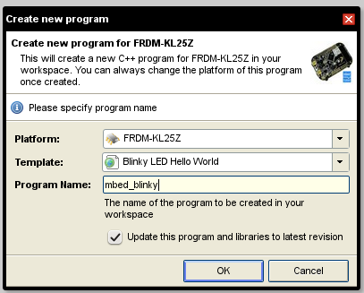
This is fairly simple as the mbed environment will do most of the work for you. Click on the compiler button and then at the top left the New >Program button. You'll get a dialog like this:

The Blinky_Hello World template is what you want. You can compile this straight away using the Compile button above the main editing panel. Down load this to the mbed and then press its reset button.
Can you make a different colour flash and change the speed ?
Exercise 2: PC output
All the mbeds offer the ability to read data back to the PC. Look at the Handbook page on Serial Comms. Here you can find an example program that allows you to write text an data back to the terminal on the pc The Task: Import the example program into your compiler and then run the terminal program on the PC (see page 1 and 2 to find out how to do this). Run the mbed program and confirm it says Hello ! Change the program so that it will respond to typing “X” with a message.
Exercise 3:
Your kl25z has plenty of external IO pins they can output current to turn on LEDs for instance. They will also sink current. Hence you can connect LEDs between two digital outputs and turn them on by setting one ouptut high and the other low.
The task: Flash two offboard LEDs in an alterntaing pattern. – modify your program from the last exercise to drive two external leds in an alternating pattern. You'll need to use the solder less bread board to mount the LEDs and two 330ohm resistors (each led needs a resistor in series to avoid excessive current draw from the mbed output).
Exercise 4:
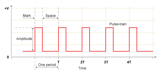
The onboard leds can be defined as PWM outputs [PwmOut myled(led1)] so that their intensity is a function of the PWM value between 0 and 1. PWM means that the output generates a square wave whose on -off ratio (or 'mark – space ratio') is controlled by the value that is written to that pin by your program. For more information checkout the mbed handbook page at https://developer.mbed.org/handbook/PwmOut

The task: Write a simple program to set the RGB led on the KL25Z to any colour and then cycle through the colours over a 5s period using the following data.
 x is a variable taking a value between 0 and 1 where 0 is red and 1 is blue.
When x=0 the colour should be pure red, when x=0.5 pure green and x=1 pure blue.
In between when x=0.25 it should be yellow (red and green) and when x=0.75 it should be cyan (blue and green).
A function that might do this for example is:

NB the KL25Z operates its onboad leds as pull downs - that means that to turn them on you set their pin to 0.... the above functions generate 1 when the color is active......
Exercise 5: Digital Input
Pins can be defined as Digital Inputs [e.g DigitalIn mypin(PTA12) ]. You can use a switch in conjunction with a resistor to set the input signal at such a pin. You use a circuit like this:
 Here the pushbutton switch will connect the pin to high and the resistor connects it to low when the switch is open. You can get +3.3V out from the mbed for the high voltage at either of the 3V3 pins although these are best not used for large signals as they are really inputs....
The task:
Connect up an external switch to allow you to switch the state of your LEDs or change the timing of their flashes.
Exercise 6: Accelerometer
The KL25Z has a couple of onboard sensors one of which is an accelerometer (using the MMA8451Q chip from TSI). These can be used as interfaces and there are nice libraries on the mbed website that offer simple methods to use them. The MMA8451Q gives three outputs for x y and z acceleration and can thus determine the tilt angle of the mbed PCB with respect to gravity.
The task:
Write a program to read the mbed accelerometer and use it to make one of the on board LEDs flash at a variable rate. With the mbed upside-down led should be flashing slowly once per second and with the mbed right way up it should pulse 10 times a second. In between the rate should increase as the board is rotated.
Exercise 7: ADC and LCD display
For the project we have a set of LCD displays that can be used to show 2 lines of text 16 characters in length. There is a nice library all ready to use for it on the mbed site called TextLCD. The KL25Z and most mbeds have a bunch of inputs that are analogue to digital converters allowing the connection of analogue sensors.
The task:
Write a program to read the a voltage (between 0 and 3.3V) presented to one of the mbed ADC inputs and display the actual voltage on the screen. (NB. To get to grips with the ADC first you could just send the readout to the computer via the pc serial link from exercise 2).
Well done – you've now completed day 1 !