You are viewing an older revision! See the latest version
Sparkfun MyoWare Muscle Sensor
The MyoWare muscle senor can be paired with the MBED to create an Electromyograph (EMG) that is capable of evaluating and recording the electrical activity produced by skeletal muscles via a difference in electric potential. EMG has a variety of traditional medical uses. It can be used to detect neuromuscular diseases among other things. This sensor allows us to think of new control applications harnessing EMG.
The sparkfun MyoWare muscle sensor kit can be purchased from Sparkfun or Adafruit. The datasheet can be located Here and a detailed instruction guide from Sparkfun can be found Here.You can either purchase the sensor as a stand alone item or it can be bought as a sensor development kit. Testing and use of this sensor will require that the user has plenty of EMG sensor pads, this is the location of the datasheet for the sensor pads. Alternatively you can make a reusable sensor pad.
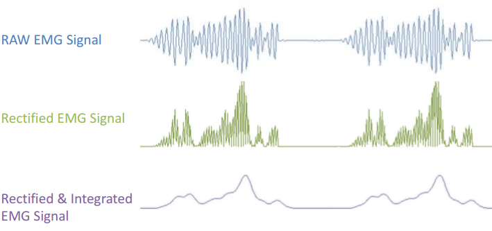
The muscle sensor itself can take an input voltage from +2.9v to +5.7v and comes with polarity protection. The sensor can be expanded via shields that are produced by Advancer. It has power and signal strength LED's for ease of debugging. It also comes with an on board potentiometer for manual gain adjustment. The output of the sensor is either a raw EMG signal or a rectified and integrated version. Please refer to the graph below for differences in outputs.

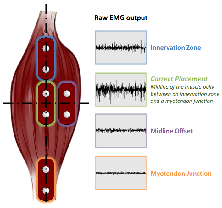
Correct placement of the electrodes is critical in ensuring that you receive a strong signal of the muscle that you wish to measure and can take several attempts. For most of the following efforts, the biceps muscle on the arm was used following the connection instructions in the datasheet. The sensor itself can be used to connect the pads to the body or with the cable shield for different applications. Please adhere to the safety information found in the datasheet about isolating the circuitry from your body.

Here is a video of one of the most popular uses of this sensor:
Hello World Test
This is a simple program to output the values of the sensor to your pc terminal. Gives values scaled between 0 and 1.
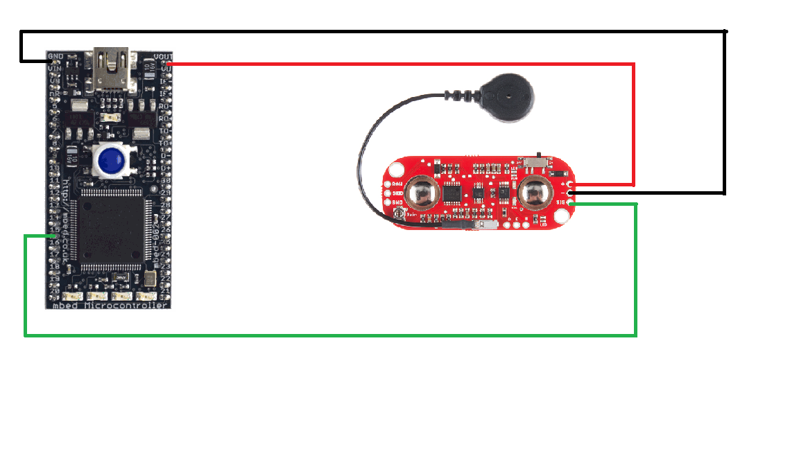
Wiring
| MBED | MyoWare |
|---|---|
| VOUT | + |
| GND | - |
| AnalogIn | SIG |
#include "mbed.h"

Serial pc(USBTX, USBRX); // tx, rx
AnalogIn sig(p15);       // Gives the rectified and integrated EMG signal

//This is a simple test of the myoware muscle sensor
int main() {

    while(1) {
        float sig_val = sig;
        pc.printf("Sig Value: %f\n\r", sig_val);
        wait(1);
    }

}
Using the Cable Shield
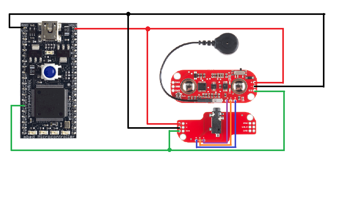
The cable shield can be used in lieu of attaching the sensor directly to your body. The shields that myoware has developed are stack able with female header pins to make a compact design. Simply plug the red (middle), blue (end), and black (ref) cables into the cable shield and attach as normal. Wiring the two together is as follows
| MBED | MyoWare | Cable-Shield |
|---|---|---|
| VOUT | + | |
| GND | - | |
| AnalogIn | SIG | |
| R | R | |
| E | E | |
| M | M |


Replacing the LED Shield
This code replicates the functionality of the LED attachment shield that can be found here using the MBED's on board LEDs. There is a resolution difference, as you are going from 10 to 4 LEDs. This is also basing the LED brightness off of the SIG connection, where the LED board appears to use the RAW version.
#include "mbed.h"

Serial pc(USBTX, USBRX); // tx, rx
AnalogIn sig(p15);       // Gives the rectified and integrated EMG signal
DigitalOut led1(LED1);
DigitalOut led2(LED2);
DigitalOut led3(LED3);
DigitalOut led4(LED4);

//This is a simple test of the myoware muscle sensor
int main() {
    led1=0;
    led2=0;
    led3=0;
    led4=0;
    while(1) {
        float sig_val = sig;
        pc.printf("Sig Value: %f\n\r", sig_val);
        if(sig_val>0 && sig_val <.25) {
            led1=1;
            led2=0;
            led3=0;
            led4=0;
        } else if (sig_val>=.25 && sig_val <.50) {
            led1=1;
            led2=1;
            led3=0;
            led4=0;
        } else if (sig_val >= .50 && sig_val <.75) {
            led1=1;
            led2=1;
            led3=1;
            led4=0;
        } else if (sig_val >= .75 && sig_val<1) {
            led1=1;
            led2=1;
            led3=1;
            led4=1;
        }
        wait(1);
    }

}
Digital Out
Using the API