Sparkfun MyoWare Muscle Sensor
Getting Started
The MyoWare muscle senor can be paired with the MBED to create an Electromyograph (EMG) that is capable of evaluating and recording the electrical activity produced by skeletal muscles via a difference in electric potential. EMG has a variety of traditional medical uses. It can be used to detect neuromuscular diseases among other things. This sensor allows us to think of new control applications harnessing EMG.
The sparkfun MyoWare muscle sensor kit can be purchased from Sparkfun or Adafruit. The datasheet can be located here and a detailed instruction guide from Sparkfun can be found here. You can either purchase the sensor as a stand alone item or it can be bought as a sensor development kit. Testing and use of this sensor will require that the user has plenty of EMG sensor pads, this is the location of the datasheet for the sensor pads. Alternatively you can make a reusable sensor pad.
The muscle sensor itself can take an input voltage from +2.9v to +5.7v and comes with polarity protection. The sensor can be expanded via shields that are produced by Advancer. It has power and signal strength LED's for ease of debugging. It also comes with an on board potentiometer for manual gain adjustment. The output of the sensor is either a raw EMG signal or a rectified and integrated version. Please refer to the graph below for differences in outputs.
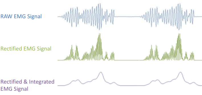
These images comes from the datasheet located here.
Connecting the Electrodes
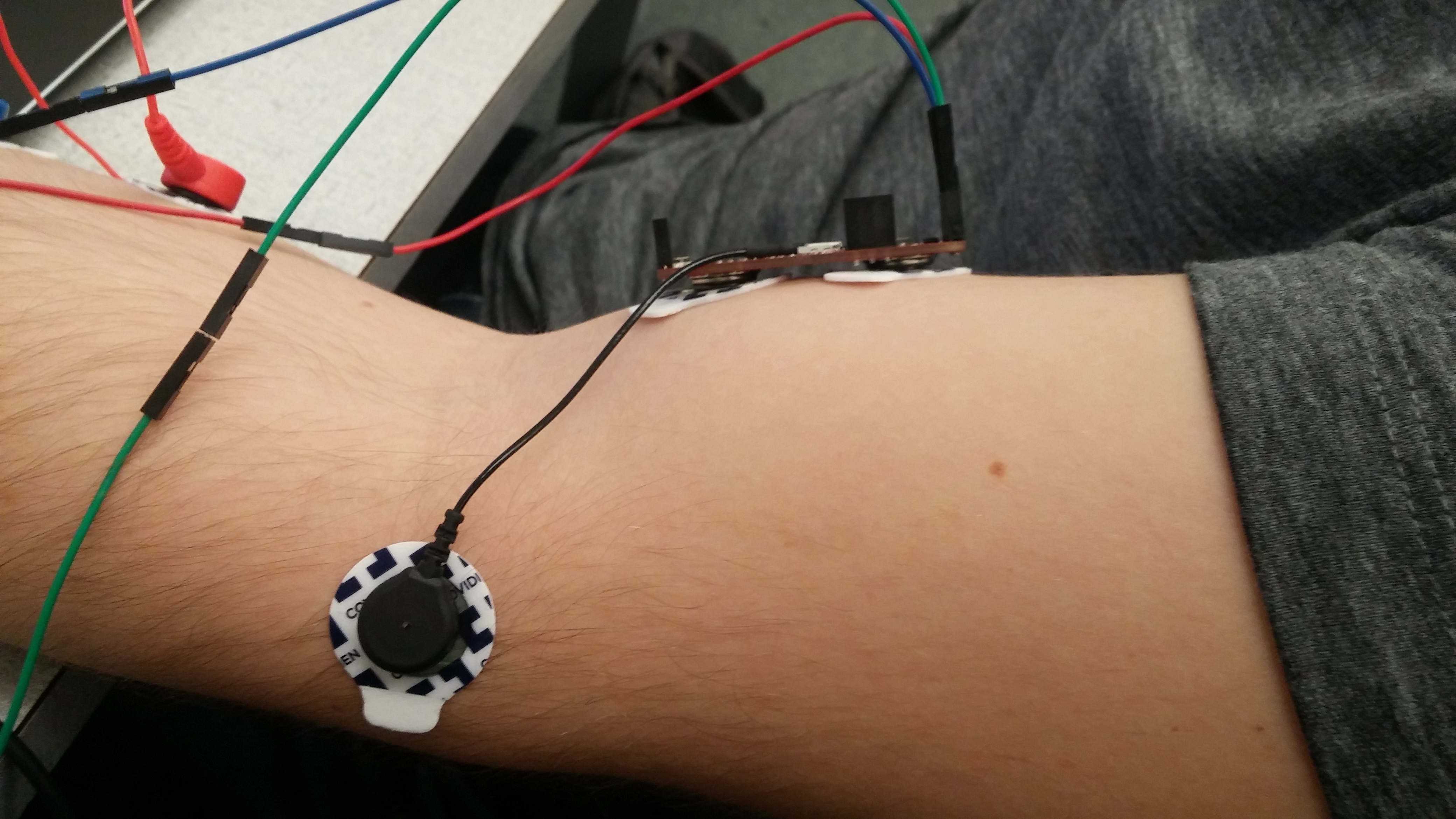
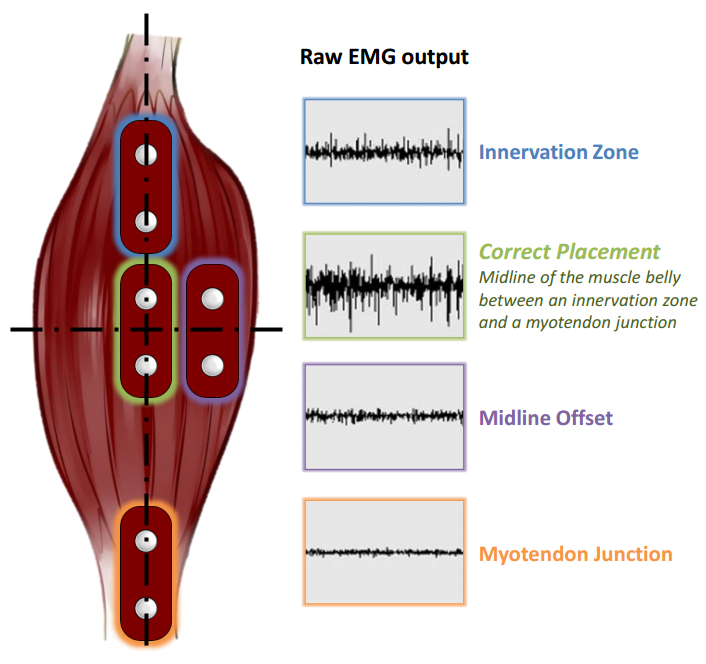
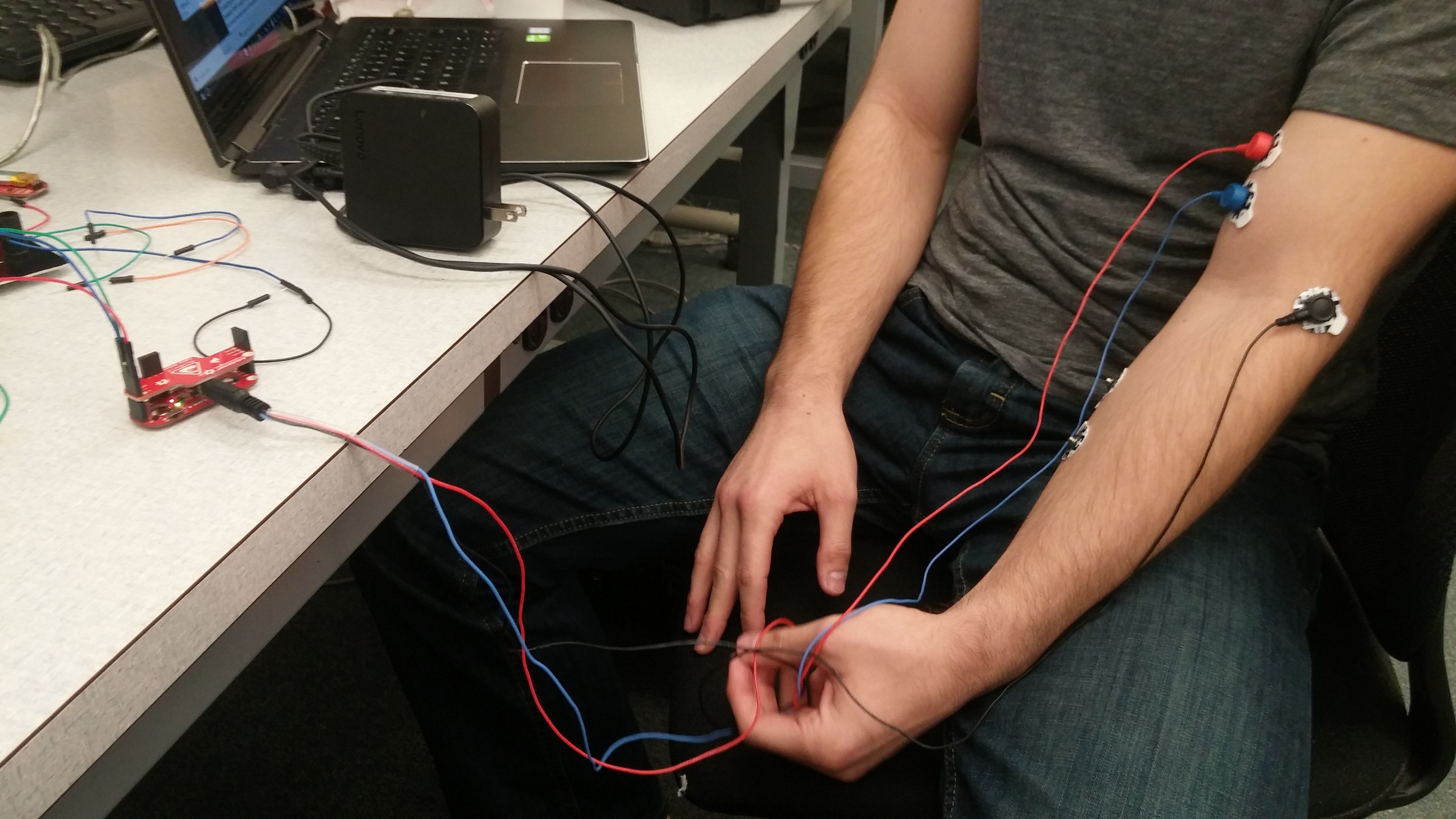
Correct placement of the electrodes is critical in ensuring that you receive a strong signal of the muscle that you wish to measure and can take several attempts. For most of the following efforts, the biceps muscle on the arm was used following the connection instructions in the datasheet. The sensor itself can be used to connect the pads to the body or with the cable shield for different applications. Please adhere to the safety information found in the datasheet about isolating the circuitry from your body.
Here is a video of one of the most popular uses of this sensor:
Example Applications
Hello World Test
This is a simple program to output the values of the sensor to your pc terminal. Gives values scaled between 0 and 1.
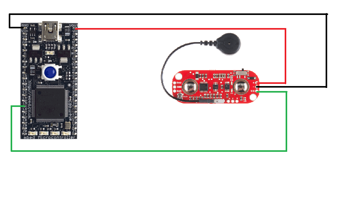
Wiring
| MBED | MyoWare |
|---|---|
| VOUT | + |
| GND | - |
| AnalogIn (p15) | SIG |
#include "mbed.h"

Serial pc(USBTX, USBRX); // tx, rx
AnalogIn sig(p15);             // Gives the rectified and integrated EMG signal

//This is a simple test of the myoware muscle sensor
int main() {

    while(1) {
        float sig_val = sig;
        pc.printf("Sig Value: %f\n\r", sig_val);
        wait(1);
    }

}
Using the Cable Shield
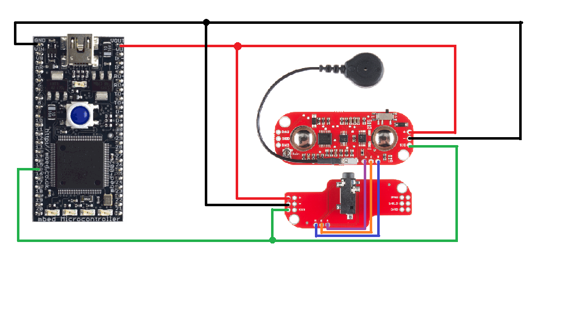
The cable shield can be used in lieu of attaching the sensor directly to your body. The shields that Advancer have developed are stack-able with female header pins to make a compact design. Simply plug the red (middle), blue (end), and black (ref) cables into the cable shield and attach as normal. Wiring the two together is as follows
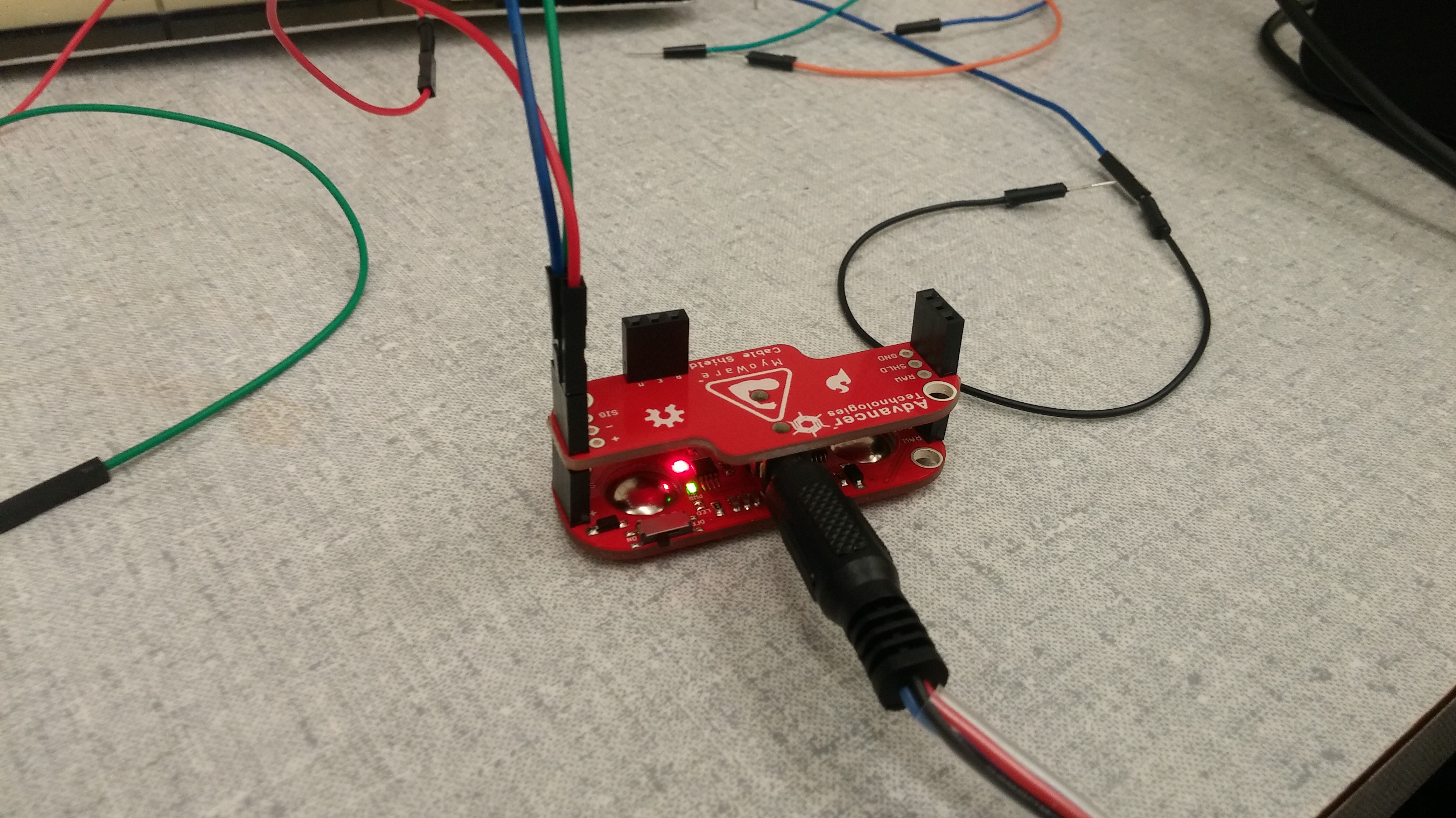
| MBED | MyoWare | Cable-Shield |
|---|---|---|
| VOUT | + | + |
| GND | - | - |
| AnalogIn (p15) | SIG | SIG |
| R | R | |
| E | E | |
| M | M |
Replacing the LED Shield
This code replicates the functionality of the LED attachment shield that can be found here using the MBED's on-board LEDs. There is a resolution difference, as you are going from 10 to 4 LEDs. This is also basing the LED brightness off of the SIG connection, where the LED board appears to use the RAW version.
#include "mbed.h"

Serial pc(USBTX, USBRX); // tx, rx
AnalogIn sig(p15);       // Gives the rectified and integrated EMG signal
DigitalOut led1(LED1);
DigitalOut led2(LED2);
DigitalOut led3(LED3);
DigitalOut led4(LED4);

//This is a simple test of the myoware muscle sensor
int main() {
    led1=0;
    led2=0;
    led3=0;
    led4=0;
    while(1) {
        float sig_val = sig;
        pc.printf("Sig Value: %f\n\r", sig_val);
        if(sig_val>0 && sig_val <.25) {
            led1=1;
            led2=0;
            led3=0;
            led4=0;
        } else if (sig_val>=.25 && sig_val <.50) {
            led1=1;
            led2=1;
            led3=0;
            led4=0;
        } else if (sig_val >= .50 && sig_val <.75) {
            led1=1;
            led2=1;
            led3=1;
            led4=0;
        } else if (sig_val >= .75 && sig_val<1) {
            led1=1;
            led2=1;
            led3=1;
            led4=1;
        }
        wait(1);
    }

}
Using the API
public:

    MyoWare(PinName pin); //Setup myoware sensor signal pin.

    MyoWare(PinName pin, float _level); //Initialize as digital out.

    MyoWare(PinName pin, float _level, int _grad);
    //Initialize as digital out.
    //Includes the gradient functionality for integer steps input.

    float read(); //Read the input value of the myoware sensor.

    bool control();
    // Returns 1 if output signal value is greater than level supplied.
    // Otherwise returns 0.

    int magnitude();
    // Accepts a step count number, and returns the value of the step which
    // the value currently resides.
    // EX. if the step count is 10, then gradient will return the interger of
    // the number of time the signal value is divisible by .1.
Digital Out
To use the tool set as a digital switch, initialize the MyoWare device with a signal analog input pin, as well as a logic level floating point value. Once the device is initialized, the control() function can be called, and if the sensor value is greater than the logic level setup during initialization, the return value will be true. Otherwise, the function will return false. This can be used as a direct pin assignment to control a DigitalOut pin with the MyoWare device.
float logic = 0.7f;
MyoWare ms(p15, logic);

p20 = ms.control();
Stepped Response
The magnitude() function will return an integer magnitude value based upon the step count which the user inputs. The step value is calculated by dividing up the 0 to 1 response by the number of steps desired, and then the integer value returned is equal to the floor of the current input value divided by the step level.
For example, if the user inputs a step count of 10, the sensor will output an integer which counts up to the total current value, divided by point .1. If the current value is .63, the function returns 6.
To initialize the MyoWare device for this function, call the device with an analog in pin, a floating logic level, and a step count integer value.
MyoWare ms(p15, logicLevel, stepNumber);
#include "mbed.h"
#include "MyoWare.h"

Serial pc(USBTX, USBRX); // tx, rx

float logic = 0.7f;
int steps = 20;
MyoWare ms(p15, logic, steps);

//This is a simple test of the myoware muscle sensor class
int main() {

    while(1) {
        float sig_val = ms.read();
        bool onOff = ms.control();
        int stepNum = ms.magnitude();


        pc.printf("Sig Value: %f\n\r", sig_val);
        pc.printf("Logic Value: %f\n\r", logic);
        pc.printf("Digital Value: %d\n\r", onOff);
        pc.printf("Total Steps: %d\n\r", steps);
        pc.printf("Step Value Value: %d\n\r", stepNum);
        pc.printf("\n\r");
        wait(2);
    }

}
Example Game Program
This code simulates a carnival strong man test where you have to flex your muscles to increase the position of the servo and your score.
| MBED | MyoWare | Servo | Power Supply |
|---|---|---|---|
| VOUT | + | ||
| GND | - | Black | GND |
| AnalogIn | SIG | ||
| Pin 22 | Yellow | ||
| Red | +5v |
The code prints commands to your terminal to tell you when to perform actions. The servo is connected (and must be) to an external 5v power supply. The led's are programmed to give you a visual indication of when to perform the actions required. In the averaging loop they are controlled by timer interrupts.
#include "mbed.h"
#include "Servo.h"

Serial pc(USBTX, USBRX); // tx, rx
AnalogIn sig(p15);             // Gives the rectified and integrated EMG signal
Servo myservo(p22);
Ticker flipper1;                  // sets up timers to control the on-board leds
Ticker flipper2;
Ticker flipper3;
Ticker flipper4;

//functions to flip the LED's on a timer
void flip1() {
    led1 = !led1;
}

void flip2() {
    led2 = !led2;
}

void flip4() {
    led3=!led3;
 }

void flip8() {
    led4 = !led4;
 }

//sample the readings for 10 seconds and return the average reading
float avg() {

    int count = 10;
    float intensity = 0;
    pc.printf("starting in 4...\n\r");
    //count down the lights from 4 to 0 {
    led4=0;
    wait(.5);
    pc.printf("3...\n\r");
    wait(.5);
    led3=0;
    wait(.5);
    pc.printf("2...\n\r");
    wait(.5);
    led2=0;
    wait(.5);
    pc.printf("1...\n\r");
    wait(.5);
    led1=0;
    pc.printf("GO!... Start flexing\n\r");
    wait(1);

    // Flash the LED's
    flipper1.attach(&flip1, .5);
    flipper2.attach(&flip2, .25);
    flipper3.attach(&flip4, .5);
    flipper4.attach(&flip8, .25);

    //give the lights time to start flashing
    wait(.5);

    //take 10 measurements of muscle activity and then return the average
    while(count > 0) {
        intensity = intensity + sig;
        pc.printf("Measuring your intensity: %f!\n\r", intensity);
        count--;
        pc.printf("Counts Remaining: %d\n\r", count);
        wait(.5);
    }
    intensity = intensity/10.0;
    pc.printf("Calculating your average intensity: %f!\n\r", intensity);

    flipper1.detach();
    flipper2.detach();
    flipper3.detach();
    flipper4.detach();

    led1=0;
    led2=0;
    led3=0;
    led4=0;

    return intensity;
}

void servo_control() {

    myservo=0;    //restart the servo to its initial position

    led1=1;           // turn on all leds until the game begins
    led2=1;
    led3=1;
    led4=1;

    bool flag=0;   // restart flag set to 0

    float intensity;

    while(flag!=1) {
        float analogValue=sig;
        pc.printf("Flex your arm to start the game!\n\r");
        wait(1);
        if(analogValue>.5) {
            intensity = avg();
            flag=1;
        }
    }

    myservo=intensity;
    wait(1);

    while(1) {
       float analogValue=sig;
       pc.printf("Waiting on you to start again!\n\r");
       wait(1);
       if(analogValue>.75) {
           pc.printf("Get ready to start again!\n\r");
           myservo=0;
           wait(1);
           servo_control();
       }
   }

}

int main() {
    servo_control();
}